Mk1 16V Conversion - Late 16V CE2 Main Wiring loom
Note: Below is if you decide to re-wire the Mk1 Completely using a late Mk2 16V loom. This referred to as a CE2 loom (Central Electrics 2) and is recognisable by having the Hazard Warning Light on the Steering Column instead of Dash. Early mk2 16V (CE1) looms have the Hazard Warning Switch on the Dash, use different fusebox connectors and some different wiring colours.
This is not strictly required and if your Mk1 is Injection already you can use the existing Mk1 GTI loom.
Mk2 16v CE2 Wiring
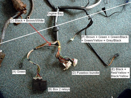
With a complete CE2 16v Mk2 Golf/Corrado Engine bay harness you will end up with the something looking like this around the fusebox area: (White Line Showing Bulkhead)

(A) Not used on UK cars.
(B) ISV (Idle Stabilisation Valve) control unit. Located behind the centre console from the donor vehicle and is part of the engine harness.
(C) Single black and Single white wire going into one of the white fusebox multi-pin connectors. Black = ignition feed, white = To ISV via Fusebox
(D) This harness is from a vehicle, which has CE2 (Central Electrics 2, hazard light on the steering column) so it is very unlike CE1 equipped vehicles which use different colours and shapes for the fusebox connectors.
The following connectors are to be found in the rain tray where you would also find the wiper motor and heater motor components.
(E) Fuel pump relay. Black = ignition feed for ECU, Red/Yellow = ####, Black/Yellow = TPS (Throttle Position Switch)
(F) Wiper motor
Label all the connectors you know you will need:
WUR - Grey
Cold Start Valve (CSV) - Blue
Thermo-Time Switch - Brown
TPS (Throttle Position Switch)
2 pin black connectors for Vacuum Switch and Cut-Off valve (found behind the air box area on the donor vehicle)
Yellow and Blue single Spade Connectors leading to oil pressure senders
Red/yellow Temperature gauge wire going to one of the coolant senders on the side of the head.
Red/black castle looking connector for the ignition coil with a piggyback connector for ISV feed.
The best approach to take with a CE2 engine bay harness (maybe wise to do the same with an early 16V K-Jet harness as well) is to completely remove the black plastic covering. Be very careful not to snip through any of the wires when you are cutting as there is a small chance you could end up adding resistance to the wires if you had to rejoin them. The ends of the black plastic are glued down, usually in 2-3 places. When you are cutting through the plastic sleeving, press down with your thumb on the main bundle of wires and proceed to cut along the roof of the sleeving making sure to remove any bumps or ripples ahead of you.
You will notice that every 20cms or so there will be a band of black tape around the wires, when you have cut the sleeving past a junction, put an extra bit of tape where the two or more groups of wires parted, so that it will be a lot easier to place around the engine if you need to check things. Most of the wiring should keep its shape anyway, i.e. where it goes around the engine block.
The next part to tackle is to trace the wires back from the various connectors to the white multi-pin connectors, which would locate into a CE2 fusebox and name the ones you can see, WUR, Thermo-Time Switch, Coil, Oil pressure etc. Not all the wires from a multi-pin connector in the engine bay will go into the same connector at the fusebox end but most will.
Now you can start to remove the wires you don’t need depending on which wires you want to use, whichever are in the best condition or existing wires that will no longer reach. You can leave the coil wiring as it is and remove this from the 16v loom, same with the oil pressure, coolant temperature, and starter motor wires if you wish. You may have to unwrap some of the black tape at this stage to get the wires out.
It will be easier now to remove the ISV wiring from the harness if you want to, which all originate from the black box (as per the picture at the top of this section labelled as B), this may help problem solving later on before rewrapping the loom. One or two wires in the engine bay may lead to a connector, which is part of the main engine harness, in particular the TPS and possibly the starter motor, so you may have to do the best you can with separating the wires and at the end if you really need to, cut a wire and rejoin if it is tangled and needs rerouting.
The ISV module is associated with the ISV (front right upper most corner of the inlet manifold above the CSV (Cold Start Valve/blue), an earth, red/black piggyback from the coil, Vacuum Switch, Cut-Off Valve and TPS.
Depending on which harness you have, there are one or two variations, some harnesses only have a 2 pin connector for the TPS (Throttle Position Switch) mounted underneath the throttle body (left side of the inlet manifold at the rear), the ’91 Corrado harness I have used a 3 pin connector.
Also on the Corrado harness there are wires for what would seem to be an Auxiliary Air Valve similar to a Mk1 GTI over on the left hand side of the engine bay near the air box, these had already been cut off on my harness so I opted to remove these as you only need one system to control the idle speed.
Contributors:
James (‘Mk1_Driver’)
There are no pages beneath this page
There are no posts yet


