K'plate clipper coolant wiring correction required
Posted
#1550617
(In Topic #207752)
Settled In


I have a K’ reg clipper which has had a webber carb fitted. I have noticed a few engine wires tapped up and some that look oddly connected.
I noticed the grey and the red coolant sensor connectors have been disconnected with a single wire to the metal coolant housing coming from the head (should it have a 2 sensor plastic housing).
Has this been done due to having a webber carb?
I will get pictures up on what wires are connected, Can anyone provide a wiring diagram with the wire colours and connector types for this model.
Thank you
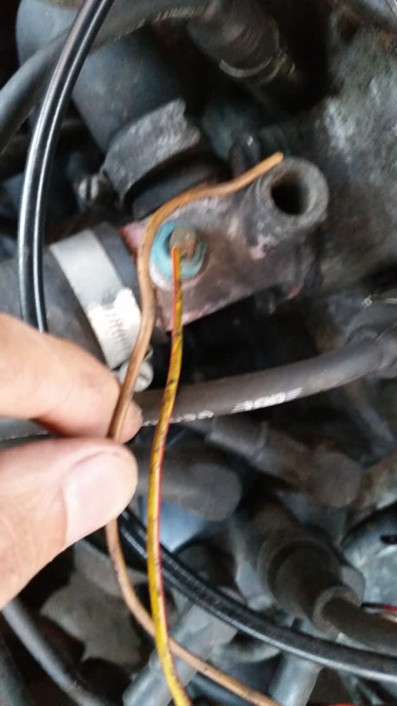
Pic 1 - DIY'd yellow/red wire on coolant sensor
Pic 2 - These connectors were tapped up which look like the ones which go to the coolant housing
Pic 3 - Shows the the red and grey coolant connector wires - were the black wires soldered together


 Last edit: by g60mvr6
Posted
Settled In


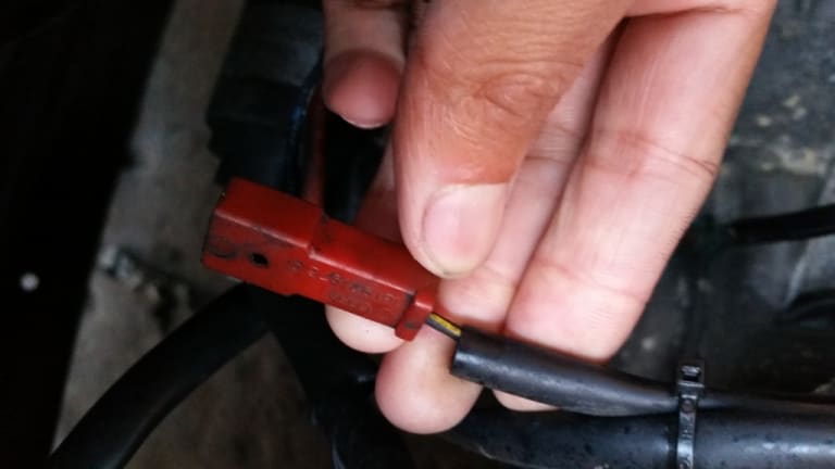
Pic 5 - Red connector with yellow/black wire not connected to anything
Pic 6 - Coolant housing has a red connector at the bottom what is this and which colour wires would connect
Pic 7 - loose brown wire roughly the same length as the yellow/red coolant wire.


Posted
MOTY 2013

1. crimp a spade on that for a proper connection
2. the grey switch is for autochoke, which the weber doesnt have. red does the inlet manifold heater, goes on thermoswitch in picture 6
3. all good, tape over the crimped joint this is a factory connection just needs insulating
4. oil pressure switch, goes to the one on the side of the head. the wire that is on the pressure switch doesnt look right, what colour is the wire
5. autochoke connection, not needed
6. crimp spades on the red 2 pin plug wires and that'll sort the inlet heater
7. thats the earth for the 2 pin black plug on the coolant temp sensor wiring which has been cut off to suit the early front flange
Hello my name is John and I'm a dub addict.
My wiring diagrams and other documents have moved here:
VAG Documents & Downloads
You'll need to sign into google/gmail for the link to work! (its free!)
My wiring diagrams and other documents have moved here:
VAG Documents & Downloads
You'll need to sign into google/gmail for the link to work! (its free!)
Posted
Settled In


rubjonny said
yeah the loom was for a late carb with plastic flange and 3x 2 pin push fit temp sensors. you have early alloy flange with spade sensors, no biggy.
1. crimp a spade on that for a proper connection
2. the grey switch is for autochoke, which the weber doesnt have. red does the inlet manifold heater, goes on thermoswitch in picture 6
3. all good, tape over the crimped joint this is a factory connection just needs insulating
4. oil pressure switch, goes to the one on the side of the head. the wire that is on the pressure switch doesnt look right, what colour is the wire
5. autochoke connection, not needed
6. crimp spades on the red 2 pin plug wires and that'll sort the inlet heater
7. thats the earth for the 2 pin black plug on the coolant temp sensor wiring which has been cut off to suit the early front flange
Hi RJ, the wire to the oil pressure switch at the moment is vio/blk (reply to your question on point 4.)
Posted
MOTY 2013

Hello my name is John and I'm a dub addict.
My wiring diagrams and other documents have moved here:
VAG Documents & Downloads
You'll need to sign into google/gmail for the link to work! (its free!)
My wiring diagrams and other documents have moved here:
VAG Documents & Downloads
You'll need to sign into google/gmail for the link to work! (its free!)
Posted
Settled In


rubjonny said
yeah thats not supposed to be on there, disconnect it
What is that connected to then?
Posted
Settled In


Posted
MOTY 2013

for the mk1 yellow goes to the head on a brown or blue 0.3/0.24bar switch, blue/black to the filter housing on a white 1.8 bar switch
they might need to go the other way round if the loom was adapted from mk2 golf or possibly very late cab looms were this way as well.
Plug it in as above first, if the oil light comes on with ignition and the oil light/buzzer stays off at high rpm then its correct. if not, swap them roudn and see
Hello my name is John and I'm a dub addict.
My wiring diagrams and other documents have moved here:
VAG Documents & Downloads
You'll need to sign into google/gmail for the link to work! (its free!)
My wiring diagrams and other documents have moved here:
VAG Documents & Downloads
You'll need to sign into google/gmail for the link to work! (its free!)
Posted
Settled In


rubjonny said
if its blue/black then thats the other oil pressure switch wire, it goes on the filter housing
for the mk1 yellow goes to the head on a brown or blue 0.3/0.24bar switch, blue/black to the filter housing on a white 1.8 bar switch
they might need to go the other way round if the loom was adapted from mk2 golf or possibly very late cab looms were this way as well.
Plug it in as above first, if the oil light comes on with ignition and the oil light/buzzer stays off at high rpm then its correct. if not, swap them roudn and see
Thank you RJ, just a last question I have a single solid red wire not connected to anything as you can see in pic 4. Any Idea where that goes please.
Posted
MOTY 2013

Hello my name is John and I'm a dub addict.
My wiring diagrams and other documents have moved here:
VAG Documents & Downloads
You'll need to sign into google/gmail for the link to work! (its free!)
My wiring diagrams and other documents have moved here:
VAG Documents & Downloads
You'll need to sign into google/gmail for the link to work! (its free!)
0 guests and 0 members have just viewed this: None.


