Messing with MFA and Eco gauge
Posted
#755784
(In Topic #90885)
Old Timer

Messing with MFA and Eco gauge
I still need to get that orange light going and ALSO need to look at a way of adjusting the MPG on the MFA.
Posted
Old Timer

Posted
Settled In

Posted
Old Timer

Posted
Local Hero


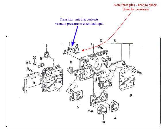
The change up light is also connected to the circular thingly next to the dizzy with a vac pipe and electrical wires connected to it. I changed mine and the light worked for the 1st time ever about 18 months ago. Its since stopped working again but thats agood thing as the light blinking on and off anit half a PITA
1983 Mars Red 1.8 Golf GTI
1987 Alpine White 1.8 Clipper Cabriolet
The trouble with doing nothing is that you never know when you are finished.
1987 Alpine White 1.8 Clipper Cabriolet
The trouble with doing nothing is that you never know when you are finished.
Posted
Old Timer


83 BBS MK1 GTI 69 T2 PANEL VAN i am back let the trouble begin 
Posted
Old Timer

I fix digital watches as a hobby and the board looks very much the same with a matrix in the middle. Its not often that the matrix fails so will investigate at a later date.
Posted
Settled In

Posted
Old Timer

I've noticed that the vaccum sensor on the Motormeter clocks are rectangular compared to the VDO clocks which are round and that the lighting is orange/yellow compared to green, the clock casing is also slightly different. I'm just wondering if the Motormeter clocks are better than the VDO as my MFA readings are now perfect!!!
Posted
Settled In

Does your experience shed any light on this?

Posted
Local Hero

92 Sportline in Flash Red, Standard **SOLD**
91 G60 Corrado in Aqua Blue pearl
91 Rallye Golf, Tornado Red, AMD tuned to 220bhp 227 flb torque 9j x16 Borbet B alloys
1985 B Alpine white mk2 Golf Gti
91 G60 Corrado in Aqua Blue pearl
91 Rallye Golf, Tornado Red, AMD tuned to 220bhp 227 flb torque 9j x16 Borbet B alloys
1985 B Alpine white mk2 Golf Gti
Posted
Old Timer

I did notice that if I removed plug 11, with all the wiring attached the outside temp would read -31, if I pluged it back in the outside temp was correct.
Posted
Old Timer

Posted
Old Timer

Posted
Settled In

M
Posted
Old Timer

I stripped the vdo clocks completely down to board level today. I removed the LCD by removing the two screws at the back, and stripped the lcd down. I noticed that a thin sheet of green plastic is between the the lcd and the clear plastic prism. I was thinking it would be possible to change the lcd from green to any colour you want by replacing it with say red plastic? I haven't tried this so I'm only guessing that it would be possible. I know it could be possible to change the colour of the rest of the display by replacing the 12"x1 green plastic strip at the top of the clocks case. Anyway going back to the blue plastic printed circuits behind the clocks, I looked at some of the tracks with a jewels eye piece and looks it corroded in places. I have not checked it out with a multimeter as yet. The PCB on which the lcd display tracks also look in poor condition close up but have not checked the tracks yet, I'm hoping that the corrosion is causing the MFA problems, because it would be easy to solder in new wires. Interestingly I've noticed an electrical adjuster is sited near to the back of the lcd, but I don't know what it does, anyone know what it does?
Posted
Local Hero

Posted
Settled In

Posted
Old Timer

I checked out the blue printed circuits and it checks out ok, dispite being in poor condition. So only the PCB to test (the board that the LCD sits on) It seems that the problems with the 99.9 mpg error and the outside temp error -31 must be down to a fault somewhere on this panel. You where right Michael in suggesting the fault may be on this panel.
Posted
Old Timer

- NEC D7507G518
- NEC D7225G
- NEC E1903K137
- HFF 4060BPS2
If the fault is in the 2 top chips it's curtains, I've never had any success in soldering in these chips.
If the fault is in chip 3 or 4 it is easy to solder in these chips and the board is savable.
To test these chips I need an electronic service manual to know the pin outs so I can check with an oscilloscope.
The other alternative I have is to replace the two chips 3 and 4 without testing to see if the error fault is retified. I think this is the road I will go down and will try and find these components. There is no point replacing chip 1 and 2 if I can't solder the micro chip.
There are too many online users to list.


