Dash Cluster Nightmare; PLEASE HELP...
Posted
#1569192
(In Topic #211187)
Settled In

hi all,
I'm hoping that some kind soul can put me out of my misery to get a mates dash cluster working again in his 1990 mk1 cabriolet 1.8i manual model…
I'll try and keep the story short but I feel its best to give all the facts so someone can hopefully help diagnose the problem. after nearly a full day searching the net for info I think I might have worked it out but I would like confirmation if possible as I can't try to fix it again until next Saturday and would like to be prepared to finish the job…
big breath in…
my friend has the above mentioned mk1 with a broken fuel gauge and jumping speedo. I kindly offered to try and fix both for him, I started with the following steps…
I popped the electrical connector off the in tank fuel sender and bridged the wires to confirm the gauge works. the fuel gauge crept nice and evenly up to the top of dial; awesome. I then removed the sender from the tank, cleaned the contacts and reconnected the sender without putting it back in the tank so i could manually move the float. I did this with the ignition on and the fuel gauge was working, at this point I was pretty happy thinking I was 50% there…
I then remove the dash cluster to see if I could see an issue with the speedo cable, it was really loose and when I removed the dash it basically fell of the back without me having to disconnect it. the only thing I disconnected was the big multi wire plug on the bottom of the cluster…
I looked for any obvious signs of damage but it all looked ok apart from a blue ribbon connector piece hanging up, I had no idea where it was meant to go and didn't want to mess with things so I left it sticking out. As I put the cluster back in ensuring I got a good positive connection on the speedo cable; I noticed another multi connector but it only had one wire coming off it. I had no idea was this was and thought it might be a spare so again I left it alone…
I shouted my friend over to brag that I'd fixed everything and when I turned the dash on and started the car, nothing happened. not a single thing. no warning lights, no rev counter, no temp gauge, no fuel gauge. my friend just looked at me as if to say, great job. He'd gone from a jumping speedo and broken fuel gauge to nothing working on the dash…
I wanted to convince him I'd fixed the fuel gauge so I jumped the wires again, this time I used the wrong pins and found out after I couldn't start the car that I'd blown the fuel pump fuse. I changed that and at least the car would start again but it still no dash cluster working…
at this point I was felling really bad, I checked all the fuses and relays without any joy, it thought I might have blown his dash up by jumping the wrong pins…
that was Saturday. I spent all Sunday googling problems but nothing matched what I was looking at. I eventually I stumbled on the thread below and noticed the photo with the second connector at the red arrows (see link below and thanks to the original poster)…
88 Cabby Cluster. I Need Adult Supervision, Please. | VW Vortex - Volkswagen Forum
I now think that the blue ribbon I have sticking out and the multi connector with a single wire in are the problem. if I just connect those two up I'm hoping for a miracle and it will all work again. I just don't want to connect them the wrong way around and as its just a ribbon sticking out its hard tell which way it goes. it looks like its come loose from behind its plastic fixing point, hopefully I can put it back there if nothings broken…
anyway I can't check again until this Saturday but I just wanted reassurance from someone that I'm on the right track. if anyone can tell me how to reattach that ribbon there's a few beers waiting for them here in Brisbane next time you're passing through…
sorry for the long post and thanks in advance…
Posted
Local Hero

Get Thee a wiring diagram for a 88, the Bentley is 87-89.
I take it you have the VDO gauge set.
The Cluster has no single wires on it. You can have up to 2 connectors, one is the back of the speedo itself it is a 2 wire connection that is for the Cruise control.
On the bottom right as you are looking at it on the car there is a Single 14 pin connector.
out of the car it is on the left.
This connector has 2 biggie Pins to take note of.
Pin2 (brown) is the ground for the whole shooting match.
Pin 14 (BLACK) is +12V in.
With the cluster out with key in and in the Run position not start.
From pin 2 to pin 14 is there 12v? yes no on the connector for the cluster. No, ok, Place your meter on a good ground any ground or earth other than pin 2.
Do you now have 12V+ on the black wire? Yes, bad ground on pin 2. No you have to find the source of the missing 12V.
If you have ground and 12v on the respective pins, attach those to the cluster and leave it so you can measure the voltage on the Cluster side of the pins.
is there 12V+ on the black wire in relation to pin 2 brown
Yes/no. yes good no you have a bad connection on one of those 2 pads.
You may need to Plump up the connector by carefully removing the shroud off the connector (I will give a link)
then place one piece of electrical tape on the pad side of the plastic tongue.
Yes are the gauges working working?
yes/no Yes your done crappy connection, you may still want to "Plump" them up.
No, then on the back of the speedo cluster there is a solid state 10 Volt stabilizer.
On this Stabilizer there are 3 pins. The middle is ground from pin2. The Bottom is 12V from pin 14. The Top is 10V.
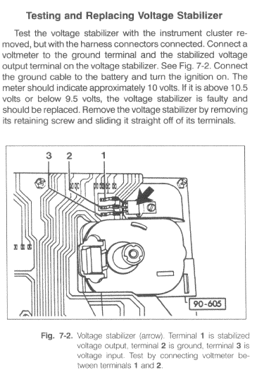
Are the respective voltages there?
Yes good your cluster should be working no?
The Place your one lead on a good earthing point other than pin 2.
Is there 12V and 10V on the proper legs?
Yes bad ground trace on the cluster.
No, then you have a bad 12V trace on the cluster after the connector pin.
10v will only be there if there is 12V on pin3 and ground on pin2. If there is 12V on pin3 and ground on pin2 then you have a bad 10V stabilizer.
The 10V stabilizer is 25-35-49 bucks at parts suppliers.
It can affect all the gauges if it goes bad the wrong way, that is shorting ground to 12V.
It provides 10V stabilized voltage reguarless of input to keep the Fuel gauge and the Water temp gauge working.
If the water gauge doesn't work, some times folks don't mention that …. then the 10V stabilizer is wonky or bad.
If you want to buy and expensive one, then go to the dealer, or parts provider… Pay out the posterior.
If you want to spend a pound or less, then you go get 2-or3 of the following from a Electronic Parts Provider. Mouser.com online but in the States (The Lost Colonies to you )… Look for a ka-7810ate.
or a lm7810… 200 or 400 mv doesn't matter.
Gauges go flaky for cold solder joints, that is they work for a few minutes then die out… Then they start working again, or they just don't work.
Here are the links as promised.
How to improve your Cluster Grounds.
http://volkswagenownersclub.com/vw/showthread.php/24949-Improving-your-Cluster-Connections-and-ground.
Fixing Flaky Water Gauges.
http://volkswagenownersclub.com/vw/showthread.php/32211-Repairing-your-Flaky-Water-Temp-Gauge
Fixing flaky Fuel senders.
http://volkswagenownersclub.com/vw/showthread.php/78890-Repairing-your-Fuel-Sending-Unit?p=600458#post600458
How to Back Feed Voltages to your cluster.
http://volkswagenownersclub.com/vw/showthread.php/60258-90ish-Cabriolet-Mylar-repair-for-10v-stabilizer.?p=531266#post531266
Hope it helps, the wiring diagram is:
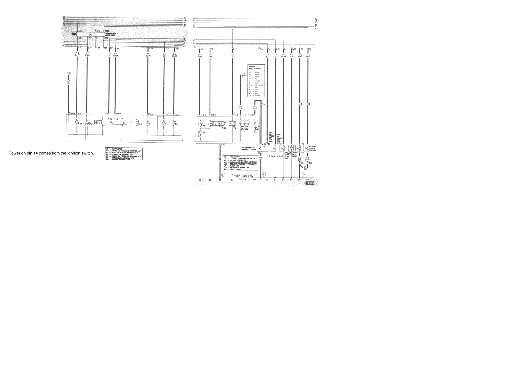
I take it you have the VDO gauge set.
The Cluster has no single wires on it. You can have up to 2 connectors, one is the back of the speedo itself it is a 2 wire connection that is for the Cruise control.
On the bottom right as you are looking at it on the car there is a Single 14 pin connector.
out of the car it is on the left.
This connector has 2 biggie Pins to take note of.
Pin2 (brown) is the ground for the whole shooting match.
Pin 14 (BLACK) is +12V in.
With the cluster out with key in and in the Run position not start.
From pin 2 to pin 14 is there 12v? yes no on the connector for the cluster. No, ok, Place your meter on a good ground any ground or earth other than pin 2.
Do you now have 12V+ on the black wire? Yes, bad ground on pin 2. No you have to find the source of the missing 12V.
If you have ground and 12v on the respective pins, attach those to the cluster and leave it so you can measure the voltage on the Cluster side of the pins.
is there 12V+ on the black wire in relation to pin 2 brown
Yes/no. yes good no you have a bad connection on one of those 2 pads.
You may need to Plump up the connector by carefully removing the shroud off the connector (I will give a link)
then place one piece of electrical tape on the pad side of the plastic tongue.
Yes are the gauges working working?
yes/no Yes your done crappy connection, you may still want to "Plump" them up.
No, then on the back of the speedo cluster there is a solid state 10 Volt stabilizer.
On this Stabilizer there are 3 pins. The middle is ground from pin2. The Bottom is 12V from pin 14. The Top is 10V.

Are the respective voltages there?
Yes good your cluster should be working no?
The Place your one lead on a good earthing point other than pin 2.
Is there 12V and 10V on the proper legs?
Yes bad ground trace on the cluster.
No, then you have a bad 12V trace on the cluster after the connector pin.
10v will only be there if there is 12V on pin3 and ground on pin2. If there is 12V on pin3 and ground on pin2 then you have a bad 10V stabilizer.
The 10V stabilizer is 25-35-49 bucks at parts suppliers.
It can affect all the gauges if it goes bad the wrong way, that is shorting ground to 12V.
It provides 10V stabilized voltage reguarless of input to keep the Fuel gauge and the Water temp gauge working.
If the water gauge doesn't work, some times folks don't mention that …. then the 10V stabilizer is wonky or bad.
If you want to buy and expensive one, then go to the dealer, or parts provider… Pay out the posterior.
If you want to spend a pound or less, then you go get 2-or3 of the following from a Electronic Parts Provider. Mouser.com online but in the States (The Lost Colonies to you
or a lm7810… 200 or 400 mv doesn't matter.
Gauges go flaky for cold solder joints, that is they work for a few minutes then die out… Then they start working again, or they just don't work.
Here are the links as promised.
How to improve your Cluster Grounds.
http://volkswagenownersclub.com/vw/showthread.php/24949-Improving-your-Cluster-Connections-and-ground.
Fixing Flaky Water Gauges.
http://volkswagenownersclub.com/vw/showthread.php/32211-Repairing-your-Flaky-Water-Temp-Gauge
Fixing flaky Fuel senders.
http://volkswagenownersclub.com/vw/showthread.php/78890-Repairing-your-Fuel-Sending-Unit?p=600458#post600458
How to Back Feed Voltages to your cluster.
http://volkswagenownersclub.com/vw/showthread.php/60258-90ish-Cabriolet-Mylar-repair-for-10v-stabilizer.?p=531266#post531266
Hope it helps, the wiring diagram is:

What do Divorces, Great Coffee, and Car Electrics all have in common?
They all start with GOOD Grounds.
Where are my DIY Links?
They all start with GOOD Grounds.
Where are my DIY Links?
Posted
Settled In

thanks a lot Briano, very informative and helpful post…
because i though i rambled on enough in my first post i did leave out some details of other test i had done…
so far i tested power to the cluster using a multi-meter on the following pins:
Pin 2 - Earth
Pin 6 - Permanent Live
Pin 14 - Switched Live
All tested good and no issues getting 12 volts with good earth…
I originally also tested the voltage stabilizer when i was looking for faults on the fuel gauge. it appeared to test well and all 3 legs gave the results as per your diagram. I tested it since the cluster stopped working and i get no voltage at all now…
i have ordered a replacement anyway but suspect that's not the issue…
http://www.ebay.com.au/itm/141976963530?_trksid=p2057872.m2749.l2649&ssPageName=STRK%3AMEBIDX%3AIT
i did notice when i was testing the fuel gauge that sometimes the dash warning lights (oil pressure / battery etc) would go out and if i tapped the cluster they would come back on…
therefore i suspect there was an original loose connection before i got my dodgy little mitts on it…
i can't post photo's on this stupid work computer but i'll update the post with photos when i get home to better explain what i'm looking at so far…
looks like i'll try to "plump" up the connector and see if that works. i did check the pins too and they look all nice and rounded instead of pushed flat…
Posted
Local Hero

Pin 6 is for the mfa, and or the clock only.
So you are looking at a ground or power issue.
Did you test both sides of the connector?
I would use a 3m Scotch lock and add a new ground to Pin 2 on the wire side direct to the frame as in my pictorials.
You may have to Back feed Ground and or Power to the 12V stabilizer if the mylar is iffy, then that would be about the best way to get everything power. If you do back feed use small wires to the legs of the 12V stabilizer, as it isn't wise to try to solder the plastic.
I am not saying that the 10v stabilizer isn't bad, it may very well be the flakey piece, I have seen solid state things to really wierd stuff over the last 46 years of playing with things…..
What do Divorces, Great Coffee, and Car Electrics all have in common?
They all start with GOOD Grounds.
Where are my DIY Links?
They all start with GOOD Grounds.
Where are my DIY Links?
Posted
Settled In

thanks again, i understand what you're saying and makes sense…
another thing that i forgot to mention is that the LCD clock on the dash works (its the only thing that does…) which suggests to me that the ground is good (pin 2) and that the live clock feed is good (pin 6)…
i only tested the feed from the connector side, i never thought to check that it was making connection with the mylar. that the first thing i'll check on Saturday morning…
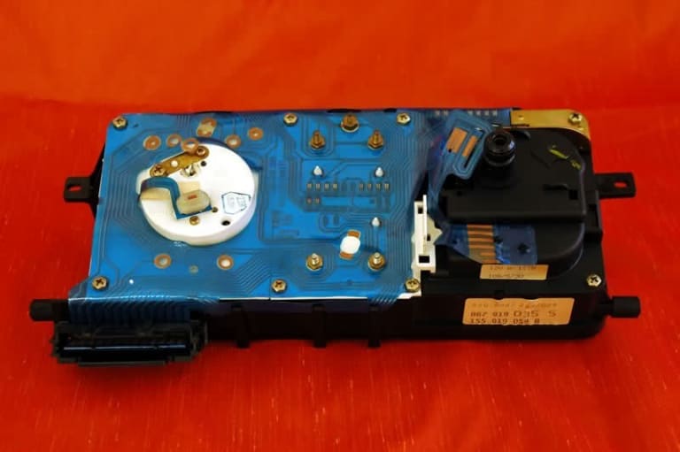
i'm still curious what the connector with one wire is for, it looks like the one in the photo below (not my photo, thanks to eBay)…
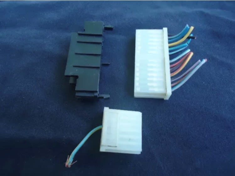
and also the mylar piece was sticking out like the photo below (thanks to eBay again) but it had two holes in it which lined up with two plastic spike so i just place it down there…
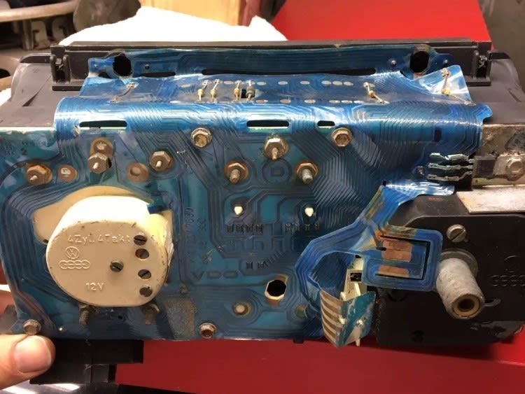
not my photo yet again but this is a good example of how i positioned the mylar my tab as it appeared to want to sit there. i'm know thinking it should be hooked up behind the white piece like in the photo above…
do you know anything about what the wire is for please, is it a spare that i don't need to worry about or should it be connected to the mylar tab (both have 6 pins)…
another thing that i forgot to mention is that the LCD clock on the dash works (its the only thing that does…) which suggests to me that the ground is good (pin 2) and that the live clock feed is good (pin 6)…
i only tested the feed from the connector side, i never thought to check that it was making connection with the mylar. that the first thing i'll check on Saturday morning…
i'm still curious what the connector with one wire is for, it looks like the one in the photo below (not my photo, thanks to eBay)…

and also the mylar piece was sticking out like the photo below (thanks to eBay again) but it had two holes in it which lined up with two plastic spike so i just place it down there…

not my photo yet again but this is a good example of how i positioned the mylar my tab as it appeared to want to sit there. i'm know thinking it should be hooked up behind the white piece like in the photo above…

do you know anything about what the wire is for please, is it a spare that i don't need to worry about or should it be connected to the mylar tab (both have 6 pins)…
 Last edit: by 6UiLE
Posted
Local Hero

What do Divorces, Great Coffee, and Car Electrics all have in common?
They all start with GOOD Grounds.
Where are my DIY Links?
They all start with GOOD Grounds.
Where are my DIY Links?
Posted
Settled In

thanks again mate, i think i have enough solutions to try on Saturday; do you know what that single wire on the 6 pin connector is for please?
Posted
Local Hero

Well that connector is used for the Airbag lights (one of them), and the Speed sensor for the Premium Radio, and Cruise
None of them have the Blue wire, and T6/4 on the Bentley Diagrams just shows a connection but nothign attached either way.
That connector is T6 which is a 6 pin connector in the diagrams whereas the larger main connector is T14 and is a 14 pin connector co-inky-dink?
None of them have the Blue wire, and T6/4 on the Bentley Diagrams just shows a connection but nothign attached either way.
That connector is T6 which is a 6 pin connector in the diagrams whereas the larger main connector is T14 and is a 14 pin connector co-inky-dink?
What do Divorces, Great Coffee, and Car Electrics all have in common?
They all start with GOOD Grounds.
Where are my DIY Links?
They all start with GOOD Grounds.
Where are my DIY Links?
Posted
MOTY 2013

as above, that is the speed signal for expensive radios, cruise control and certain ECU plus the airbag system. usually it is yellow/white, but sometimes on very late ones it is blue/white. so in short, ignore it absolutely nothing to do with your issues.
look at the black wire next on the 14 pin plug, its the ignition live. it is fed direct from the back of the ignition switch, which is a prime area for captain bodger to have a go at 'repairs' so start there and chase it back.
look down the end of the clock plug at all the pins, they often squish down a bit and make poor contact so make sure everything is ok. if it looks bad flip the back of the plug open and the terminals are then free to come out the back. pull 1 at a time making careful note of where it came from, then tweak the terminal till its the right shape, buff up if corroded. Just be careful of the red wire thats your permanent live, dont want to short that to anything. to be 100% safe pull the clock fuse before you do anything, when the lcd goes dead you know there are no live feeds to the cluster and its safe to begin work (have the ignition off too obviously!!)
Hello my name is John and I'm a dub addict.
My wiring diagrams and other documents have moved here:
VAG Documents & Downloads
You'll need to sign into google/gmail for the link to work! (its free!)
My wiring diagrams and other documents have moved here:
VAG Documents & Downloads
You'll need to sign into google/gmail for the link to work! (its free!)
Posted
Settled In

thanks Briano and rubjonny for all your help and advice. sorry its taken so long to get back but got forced in to attending a wedding last weekend which resulted in many drinks and no much car tinkering…
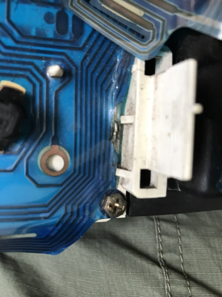
long story short I found the problem, after trying numerous fixes mentioned above I finally noticed a break in the mylar for the switched live. completely my fault but let it be a lesson to others to use your peepers a bit more and have a good look before jumping to all other technical conclusions…
just to close the thread and may be assist others with similar issues, this is what the break looked like. also looks like a previous repair didn't hold to well. Its all soldered up now and working like a champ, thanks again…

0 guests and 0 members have just viewed this: None.


