Help confused- Timing marks
Posted
#1548994
(In Topic #207422)

Settled In

Could someone please assist me. After 10 years of no mechanical problems the day I was hopefully going to sell it the head gasket went and dumped the contents of the radiator about a mile from the railway station I was due to pick the buyer up from.
Got a new victor Rienz head set, bolts , belt and oil and filter. Head is off going to be pressure tested tomorrow and if it is not cracked , skimmed. Although it is not warped. I took the head to my neighbours college on Saturday morning and set it up on a marking table and checked it thoroughly with a DTI . Less than 0.001" (0.02mm) run out end to end in both planes.
The problem I have is that whilst I set up the timing marks before I removed the cam belt , The cam sprocket and crankshaft pulley were aligned correctly, the dizzy rotor arm leading edge was just in line with the notch on the body ( is it supposed to be the centre of the rotor arm contact area that is lined up or is the leading edge as I think correct ?) secondly. the flywheel mark was 2-3 degrees out I estimate. I have not checked No 1 with a DTI yet to see if it is actually at TDC.
I have not done one of these DX engines before but the others I have worked on including V18 10 MegaWatt diesel engines the timing marks have always had to lined up spot on
I have misplaced my Brown Haynes manual (I have another coming on Tuesday) So was doing it all from memory.
Can anyone shed any light?
Cheers
Posted
Local Hero

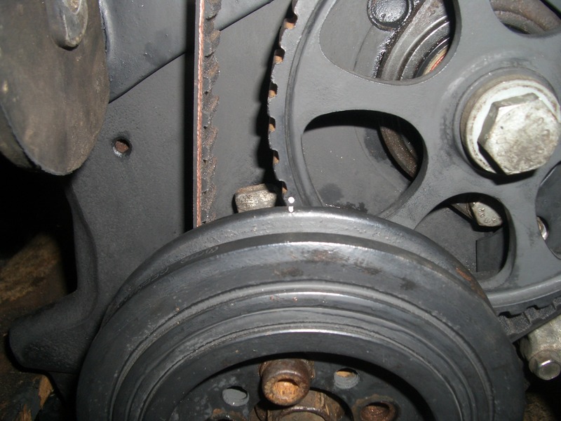
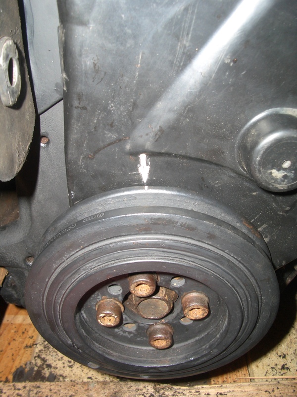
My 1988 DX engine.
Crank and intermediate shaft with cover off.

Cam shaft.

Crank with cover fitted as there is a arrow there, I had painted all my marks so easy to see.

1988 Mk1 Golf GTi Cabriolet 1.8cc DX, K-jet. Daily drive. 317,000 miles and counting
1978 Mk1 Scirocco GLS 1.6cc FR, Webber carb. Weekend toy.
1978 Mk1 Scirocco GLS 1.6cc FR, Webber carb. Weekend toy.
Posted

Settled In

I aligned the crank and camshaft pulley with the marks on the covers then checked the dizzy and flywheel and they did not look as I thought they should. Thanks again. I get my manual delivered tomorrow and get the head back today all being well
Cheers
Posted
MOTY 2013

with the rotor arm this shouldn't line up exactly to the notch, just be reasonably close. it should be set 6degrees BTDC. It might be the int shaft marks are a tooth or so off, but this doesnt matter the important thing is the position of the rotor arm.
for this stage you just want it close enough so the engine can fire, then once warmed up disconnect and plug the vacuum line to the dizzy and adjust it till the big diamond on the flywheel lines up with the marker on the gearbox bellhousing
Pic here, 6 degree BTDC diamond is shown lined up, TDC marker just to the right:

Hello my name is John and I'm a dub addict.
My wiring diagrams and other documents have moved here:
VAG Documents & Downloads
You'll need to sign into google/gmail for the link to work! (its free!)
My wiring diagrams and other documents have moved here:
VAG Documents & Downloads
You'll need to sign into google/gmail for the link to work! (its free!)
Posted

Settled In

0 guests and 0 members have just viewed this: None.


