


My latest project MK1 1.8t Quattro Build

Posted

Settling In

My latest project MK1 1.8t Quattro Build
Now that I have the final position worked out for my subframe, I know where I need to come through with the steering column. My original plan was to use the TT column so that I could retain the steering angle sensor etc and keep the ESP system and ABS, but I've since decided to go with standalone engine management, so I don't need any of that, the golf column should work fine with the bottom UJ from the TT.
I set about removing all the brackets for the brake and clutch pedals from the golf column to make way for a bias pedal box.
There was already a bit of rot up above where I wanted to mount the pedal box, so I chopped that out and replaced it with something more substantial to stiffen up that whole area

Finished the pedal box mounting frame


Pedal box mounted, and TT throttle pedal fitted


Sent from my M2007J17G using Tapatalk
I set about removing all the brackets for the brake and clutch pedals from the golf column to make way for a bias pedal box.
There was already a bit of rot up above where I wanted to mount the pedal box, so I chopped that out and replaced it with something more substantial to stiffen up that whole area
Finished the pedal box mounting frame
Pedal box mounted, and TT throttle pedal fitted
Sent from my M2007J17G using Tapatalk
Posted
Settling In
Just had a quick read through ove rmy lunch, what a project, can't wait to see progress - good luck!! 
Posted
Settled In

Some epic work going into this! I’m just on doing my pedal box at the moment and glad to see we have had the exact same idea - still collars mounted up into a strengthened rain tray - hopefully it hold up haha! Mine that is not yours, looks a lot more sturdy😂
Looking forward to the next update!
Looking forward to the next update!
'78 Golf LS 20vt
‘08 Mk5 Edition 30 DSG
‘08 Mk5 Edition 30 DSG
Posted
Settling In
Re:
Thanks man [emoji1303]white_78 said
Some epic work going into this! I’m just on doing my pedal box at the moment and glad to see we have had the exact same idea - still collars mounted up into a strengthened rain tray - hopefully it hold up haha! Mine that is not yours, looks a lot more sturdy[emoji23]
Looking forward to the next update!
I've actually progressed quite a way since my last update, I'll try and get around to posting some updates later on (I've got a ton of photos, but they're all mixed up from transferring to a new phone so I've been putting off trying to get them in some sort of order and making a post [emoji1787])
Sent from my M2007J17G using Tapatalk
Posted
Settled In
frug said
[Thanks man
I've actually progressed quite a way since my last update, I'll try and get around to posting some updates later on (I've got a ton of photos, but they're all mixed up from transferring to a new phone so I've been putting off trying to get them in some sort of order and making a post)
Sent from my M2007J17G using Tapatalk
Class, looking forward to seeing the progress!
I was looking back over my project and half of my photos were on photo bucket from the old days 😂, will need to recover them somehow!
'78 Golf LS 20vt
‘08 Mk5 Edition 30 DSG
‘08 Mk5 Edition 30 DSG

Settling In
��Not sure just how , but i've lost a few months worth of photos, heres where it stands so far…
The propshaft tunnel has been chopped about a little and is bolted in its final position (obviously it will be �welded, but i'll leave that for later, just in case)
Engine mounts have been fabricated, and the front half of the prop from the centre bearing forward fits nicely.
One of the issues i've come across is, due to the alignment of the prop and clearance of the steering rack, my inlet manifold isnt going to 'fit under the bonnet, because of the prop , i can't tilt the or lower engine much like you can in a FWD application. It took some thinking about, but i have a solution, more on that later…
I've sourced a turbo and exhaust manifold.
Bonnet and front wings test fitted along with standard front TT brakes and some 16"� BBS reps to check everything clears and looks good
MK2 GTI radiator sourced and test fitted.
Various other goodies bought and stockpiled.
�Heres a few pics of the front end all dressed up not sure if the wheels will be my final choice, but they were cheap enough, and local so i grabbed them. I quite like the look of them on the car though.


�
The propshaft tunnel has been chopped about a little and is bolted in its final position (obviously it will be �welded, but i'll leave that for later, just in case)
Engine mounts have been fabricated, and the front half of the prop from the centre bearing forward fits nicely.
One of the issues i've come across is, due to the alignment of the prop and clearance of the steering rack, my inlet manifold isnt going to 'fit under the bonnet, because of the prop , i can't tilt the or lower engine much like you can in a FWD application. It took some thinking about, but i have a solution, more on that later…
I've sourced a turbo and exhaust manifold.
Bonnet and front wings test fitted along with standard front TT brakes and some 16"� BBS reps to check everything clears and looks good
MK2 GTI radiator sourced and test fitted.
Various other goodies bought and stockpiled.
�Heres a few pics of the front end all dressed up not sure if the wheels will be my final choice, but they were cheap enough, and local so i grabbed them. I quite like the look of them on the car though.
�
Posted
Settling In
A few around the engine bay,…


The turbo is a Holset, its a bit of a mish mash of bits, but is eseentially a HX35 compressor and non wastegate quick spool� exhaust housing with a watercooled HX38 centre cartridge. I reckon it'll blow a more than sensible amount of horsepower as is, but can be upgraded pretty cheaply and easily if need be. The manifold is a cast T3 with external wastegate, its chinese, but actually looks half decent quality
�
Settling In
�Whilst the engine was in, I thought I may as well deal with the inlet manifold situation. I'd already decided water to air chargecooling was the way i wanted to go, you can mount the rad just about anywhere you can get good airflow, and they're very efficient. I decided I will� combine the chargecooler and manifold into one unit. I'm no TIG welder, so i'll get someone who knows what they're doing to dab it all together. the throttle body is around 70mm (I think) and came from a Mazda RX8. Most of the bits were cut on a table saw and filed/ sanded to get a nice fit. I turned the throttle body adapter up on a lathe and used a router to port match and flare it with the throttle body. The 4 threaded bosses above the intake runners are for water/meth nozzles.
Its kind of hard to illustrate how it all goes together without being able to weld it myself, but hopefully you'll get the idea.


�
Its kind of hard to illustrate how it all goes together without being able to weld it myself, but hopefully you'll get the idea.
�
Posted
Settling In
Happy with how everything was going at the front of the car, and knowing all the larger items will fit where in want them, I moved onto the rear end.
I made a frame from 50mm box section to go around the boot floor and get some strength into that area, the side sections going around the inner arches were made by tracing card templates and then using them to transfer marks onto the box section for the pie cuts needed to make the bend.
The whole frame was then welded into the boot floor and chassis legs, and plated up into the inner arch.
Confident nothing was gonna move, i pulled the engine/box out and removed the front suspension, and then lifted it back onto the rotisserie, before getting brave and starting chopping out a bit more excess golf.


�
I made a frame from 50mm box section to go around the boot floor and get some strength into that area, the side sections going around the inner arches were made by tracing card templates and then using them to transfer marks onto the box section for the pie cuts needed to make the bend.
The whole frame was then welded into the boot floor and chassis legs, and plated up into the inner arch.
Confident nothing was gonna move, i pulled the engine/box out and removed the front suspension, and then lifted it back onto the rotisserie, before getting brave and starting chopping out a bit more excess golf.
�
Posted
Settling In
I made some quick'n'dirty temporary adjustable control arms for the rear suspension, this took quite a bit of thinking about , as there were numerous issues to overcome to get things to work how i wanted.
In its standard width, the whole rear end is obviously far too wide to just 'fit' in there, so i had to narrow things down a little to get somewhere close to the correct width, however, the mounting points for the trailing arms �were still too far apart and would have been close to the outside of the sills, which isnt a particularly strong area, and would make some of the trailing arm visible when looking at the side of the car. The only solution i could come up with was a bit of a compromise, but im confident it will be fine.
I narrowed the suspension a further 60mm each side, this isnt quite as simple as you might think, as the control arms are angled back slightly, so removing 60mm will narrow it slightly less than that. I'm pretty sure Pythagoras has some sort of theorem that would allow me to calculate this myself, but i trial and errored it� The missing 60mm was put back with a wheel spacer on each side,
Im not really a fan of wheel spacers, and im not proud of myself, but sometimes you just gotta do what you gotta do, and, props to the company that made them, they look quality and were CNC'd up to my spec within a fortnight.
My completed suspension 'jig'


In its standard width, the whole rear end is obviously far too wide to just 'fit' in there, so i had to narrow things down a little to get somewhere close to the correct width, however, the mounting points for the trailing arms �were still too far apart and would have been close to the outside of the sills, which isnt a particularly strong area, and would make some of the trailing arm visible when looking at the side of the car. The only solution i could come up with was a bit of a compromise, but im confident it will be fine.
I narrowed the suspension a further 60mm each side, this isnt quite as simple as you might think, as the control arms are angled back slightly, so removing 60mm will narrow it slightly less than that. I'm pretty sure Pythagoras has some sort of theorem that would allow me to calculate this myself, but i trial and errored it�
The missing 60mm was put back with a wheel spacer on each side,Im not really a fan of wheel spacers, and im not proud of myself, but sometimes you just gotta do what you gotta do, and, props to the company that made them, they look quality and were CNC'd up to my spec within a fortnight.
My completed suspension 'jig'
Posted
Settling In
Binned some more chunks of golf, and did some dodgy upside down suspension fitting. My plan (if you can call it that) is to remove what is needed to get into roughly the correct position, and make plates to fit the trailing arm mounts and the haldex cradle and then do some more precise positioning and alignment later when im ready to weld in. For the moment, rough measurements and eyeballing will do.
Rather suited with how its coming together.
Next job is to modify my jig so i can try the propshaft in, as this will dictate the angle of the haldex cradle.


Rather suited with how its coming together.
Next job is to modify my jig so i can try the propshaft in, as this will dictate the angle of the haldex cradle.
Posted
Settling In
With the jig modified, its time to check the propshaft.
I'd already been around it with a tape measure, and had a fair idea it was going to be pretty close to fitting, but i couldn't believe this stroke of luck…. with the centre bearing in the middle of its slots, the prop is almost exactly where i want it.
 �
�
 �
�
 ��
��

I'd already been around it with a tape measure, and had a fair idea it was going to be pretty close to fitting, but i couldn't believe this stroke of luck…. with the centre bearing in the middle of its slots, the prop is almost exactly where i want it.
�
�
��
Posted
Settling In
My next job was to make a box section mount for the haldex cradle and some mounting plates for the trailing arms. Four discs were cut out with a 3" hole saw, and captive nuts welded on, these were then centred in the bushes with M12 threaded bar with a bit of hose slipped over it.


I then built the top frame out of 25x50mm box and welded it to the top of my captive nut plates

Mounting plates for trailing arms were traced off the original TT parts which i'd cut out of the car


�
I then built the top frame out of 25x50mm box and welded it to the top of my captive nut plates
Mounting plates for trailing arms were traced off the original TT parts which i'd cut out of the car
�
Posted
Newbie


Fantastic, where you at with this now frug
Posted
Settling In
micky1 said
Fantastic, where you at with this now frug
Things are moving along nicely Micky…..
Updates to follow
Posted
Settling In
Now that the tunnel is definitely where i want it, and while the shell was still on its stands and level, I wanted to get a bit of extra strength in. I had a pair of 'Z' shaped sections folded up in 1.5mm steel by a local fabricator, these were then trimmed to length and made to fit along the inner sills and plug welded in.


Made up a couple of crossmembers to tie the sills into the tunnel and support the floor, I don't need them welded in yet, but they'll come in handy later.


Made up a couple of crossmembers to tie the sills into the tunnel and support the floor, I don't need them welded in yet, but they'll come in handy later.
Posted
Settling In
One job that has been sat at the back of my mind niggling me was the front shocks. I've been using the TT shocks for mocking up, but they're far too long for the job, and fully bottomed out were about the length I needed for my ride height.
I spent literally hours searching the internet trying to find something suitable, or close to suitable with some modification, but came up with nothing. I'd been hoping to get some made up by AVO as we'd had a good relationship with them at work, but, it seems they've gone bust….
So it was time to get creative.
It turns out the Mk1 Golf uses about the shortest shock inserts available, so i got myself a pair of Koni adjustable inserts and some seamless tube to make the shock lower legs from, Rally design supplied the weld on spring perches, I'll leave these until i have my spring weight and length sussed before i commit to welding them.

The TT hubs have a small step that the shock absorber body rests on , ensuring it can't slip through, i die-ground this away as i wanted to get as much of the shock poking through the hub as possible. The more height i save here reduces the chance that I'll have to raise the strut tops, which, if possible, I would like to avoid.
The OD of my tube is a nice fit on the spring perches, but is a bit too large to fit the hubs, so some lathe work was needed to turn the bottom to the right size. I also bored out the inside of a pair of spacers to hold the dampers central in the shock absorber bodies.


�
I spent literally hours searching the internet trying to find something suitable, or close to suitable with some modification, but came up with nothing. I'd been hoping to get some made up by AVO as we'd had a good relationship with them at work, but, it seems they've gone bust….
So it was time to get creative.
It turns out the Mk1 Golf uses about the shortest shock inserts available, so i got myself a pair of Koni adjustable inserts and some seamless tube to make the shock lower legs from, Rally design supplied the weld on spring perches, I'll leave these until i have my spring weight and length sussed before i commit to welding them.
The TT hubs have a small step that the shock absorber body rests on , ensuring it can't slip through, i die-ground this away as i wanted to get as much of the shock poking through the hub as possible. The more height i save here reduces the chance that I'll have to raise the strut tops, which, if possible, I would like to avoid.
The OD of my tube is a nice fit on the spring perches, but is a bit too large to fit the hubs, so some lathe work was needed to turn the bottom to the right size. I also bored out the inside of a pair of spacers to hold the dampers central in the shock absorber bodies.
�
Settling In
Unfortunately, it looks like i forgot to take any photos of the work around the rear end whilst i was doing it, but I'll post what i have.
I used some temporary tags tacked on to the trailing arm mounting plates to hold them in place whilst i check everything is aligned and im happy with how everything fits and looks, and then welded the haldex frame in place.


 �
�
I used some temporary tags tacked on to the trailing arm mounting plates to hold them in place whilst i check everything is aligned and im happy with how everything fits and looks, and then welded the haldex frame in place.
�
Posted
Settling In
Back on the rotisserie for the frame welding in, theres a couple of extra supports which still need to go in, but i had run out of rectangular box section. I'll put these in when i next have a day welding up.


Posted
Settling In
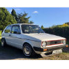
Put the car back the right way up and stuck some bits back on so I could have a look.


0 guests and 0 members have just viewed this: None.