Fuel Sending Unit Help - Tests Run Yet I May Be Missing Something
Posted
#1632792
(In Topic #224479)
Newbie

Requesting your help after following many guides on the site and talking to Briano1234 I am still facing issues.
First post after lurking for a couple of weeks. I recently started working on a 1990 Cabriolet and have come to an impasse with the fuel sending unit. I have not posted a self-bio or photo of the car yet however in short, 53 years old and shade tree mechanic who uses forums and Bentley manuals for repairs. I’m just not confident with electrical and tend to get confused easily in areas I’m unsure of.
I tend to ramble on so I’ll do my best to keep this as concise as possible yet do understand if someone helping needs more information or confirmation of steps I’ve done. Frankly, I believe I’m missing something simple, forest for the trees syndrome, and hope those that read this can find my oversight.
I want to first thank Briano1234 for his guidance including that posting may reveal more than he can about my issue. His post was helpful https://www.volkswagenownersclub.com/threads/repairing-your-fuel-sending-unit.78890/#post-600458 as was his guidance in PM.
So here we go.
1. Water temp works.
2. From what I have experienced, the rest of the instrument cluster works as well as lights, rear defroster, hazards, fasten belt light.
3. Fuel gauge works – tests read about and performed
a)9V battery to posts on back of cluster success
b)9V battery to violet/black and ground on plug in rear seat success
c)In tank fuel pump gets power and runs when connected to the sending unit.
d)“Needle” and VDO board cleaned until no black residue comes off.
b)9V battery to violet/black and ground on plug in rear seat success
c)In tank fuel pump gets power and runs when connected to the sending unit.
d)“Needle” and VDO board cleaned until no black residue comes off.
e)Continuity exists for the small/tiny blue or green colored wire on the VDO board that is connected to the pin in the 3-prong plug that corresponds with the violet/black wire
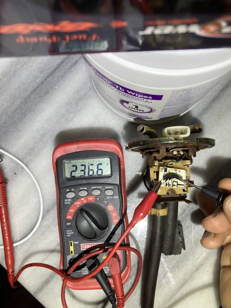
f)Placing my meter onto the two outer plug pins on the 3-pin connection on the sending unit and moving the “needle” on the VDO board to change the fuel level results in numbers from just over 300 when empty to under 100 when full.
4. When I plug in the sending unit with the in-tank pump attached and turn the key to On, not start, I get power to the in-tank pump. I manually move the float for the sending unit and no movement on the fuel gauge. The same behavior happens without the in-tank pump plugged into the sending unit.I will post pictures for those that need them, please just let me know which ones would help so I don’t bog this post with pictures, yet. Just words, HA!
Thank you all in advance for any support you can give.
Posted
Settled In

 Last edit: by Steve1973
Posted
Newbie

I just went out and put a wire in the female end of the plug to violet/black and ground and then turned the key to on and touched the wires together. There was no movement in the gauge. Note: with a 9v battery and touching the two wires to it, the gauge moves.
Your help with how to check the resistance, where to put my leads, is appreciated.
I have tested continuity by touching the leads to the ground pin and the sender as well as the violet/black to the small/tiny blue or green wire going to the VDO and I get a tone but haven't noted the numbers I get. If that is what you mean please let me know and I can provide those. Mainly I just need to know where to place the leads on the sender to read resistance and give it to you and others for reference.
Thanks again,
Ken
Posted
Local Hero

To test it assembled you remove it from the tank, insert your DVOM leads as described, and move the arm looking for resistance to vary from a low of 36 Ohms to 300 Ohms… that is the more resistance the emptier your tank, and the Smaller resistance the Higher the fuel is in your tank.
You can do the same tests as below with the PCB mounted, just insert the Negative DVOM in to the Plug ground, and the Positive lead in to the Violet/black plug pin. Then watch for the Ohms to go from a low to high or High to low. as you move the float arm.
Down scale the flow should be 36 owns (full tank) float is highest point of the arc.
Up scale 302 ohns should be empty tank as the float is the lowest point of the arc
On your circuit board of the sender.
Place the positive lead of your dvom on the left. I held it with a gator clip.
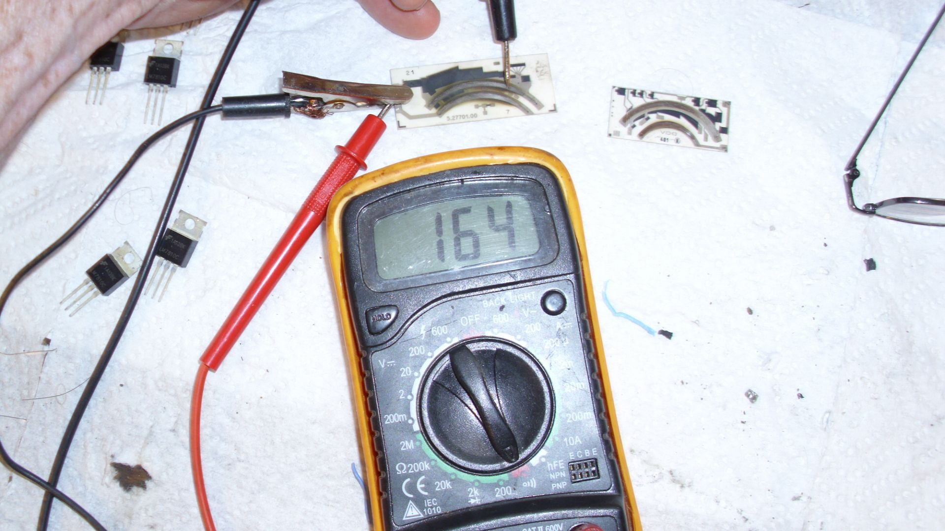
You should be at the right of the sweep and see about 300 ohms.
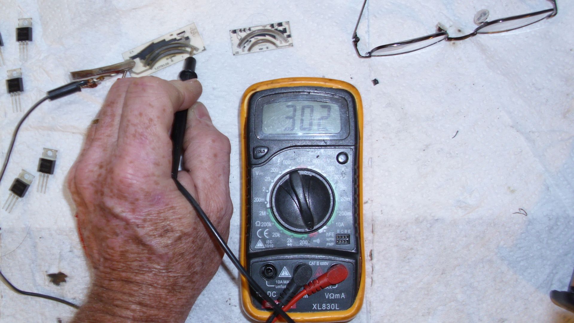
On the side nearest the Positive clip you would see about.
36 Ohms.
It could be that the wires from the PCB to the ground or the Violet/black wire or the pin are cold soldered.
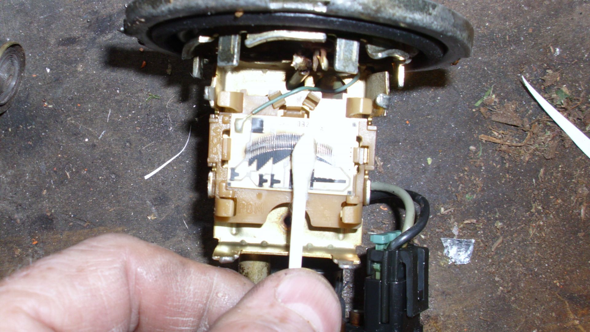
You verified that the gauge works.
You have verified via the battery test that the wires from the sender to the Gauge will deflect the gauge. What is the unknown now is the Senders Ohm readings to the plug of the sender unit.
Make sure that your sweep arm is touching the resistance sweep and that your sweep arm isn't away from the sweep….
 Last edit: by Briano1234
What do Divorces, Great Coffee, and Car Electrics all have in common?
They all start with GOOD Grounds.
Where are my DIY Links?
They all start with GOOD Grounds.
Where are my DIY Links?
Posted
Settled In

1. Check your brown at the sender is grounded with a multimeter (continuity to a known good ground).
2. Check for continuity of the violet/black between the sender and the instrument cluster connector and one of the nuts on the fuel gauge.
3. Check that one side of your fuel gauge(nut on back) has 10v (between nut and good known ground).
Check your ground to the instrument cluster(usually brown).
Posted
Local Hero

http://www.toplessrabbit.com/forums/viewtopic.php?f=7&t=3212&p=27615#p27615
Hope I answered more of your questions.
What do Divorces, Great Coffee, and Car Electrics all have in common?
They all start with GOOD Grounds.
Where are my DIY Links?
They all start with GOOD Grounds.
Where are my DIY Links?
Posted
Newbie

I read up on cold solder and agree perhaps that is part or all of my issue and it will take me a bit to venture into resoldering. So I'm going with the multimeter pieces first.
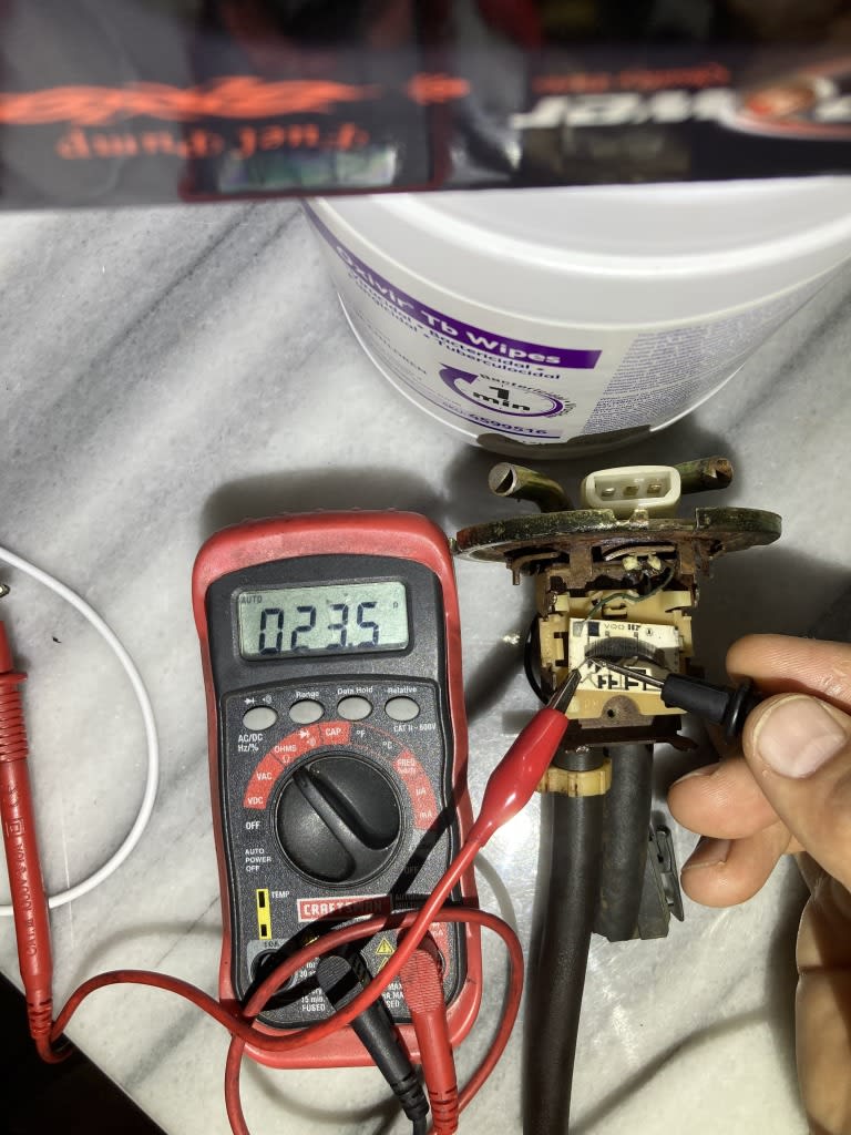
I can get readings similar to yours when I put my leads on the PCB. When I am not attempting to video I get a high of 236 and low of 23 and corresponding increasing or decreasing numbers as I move the lead like the "needle" on the float. When I am trying to video, well if it comes over you'll see. I can get 236 but as I move it "down" as if spending fuel, it will give me OL then I move my lead a bit and it will register an expected lower value and I keep moving and it will be fine then go OL again. If my videos work you'll see.
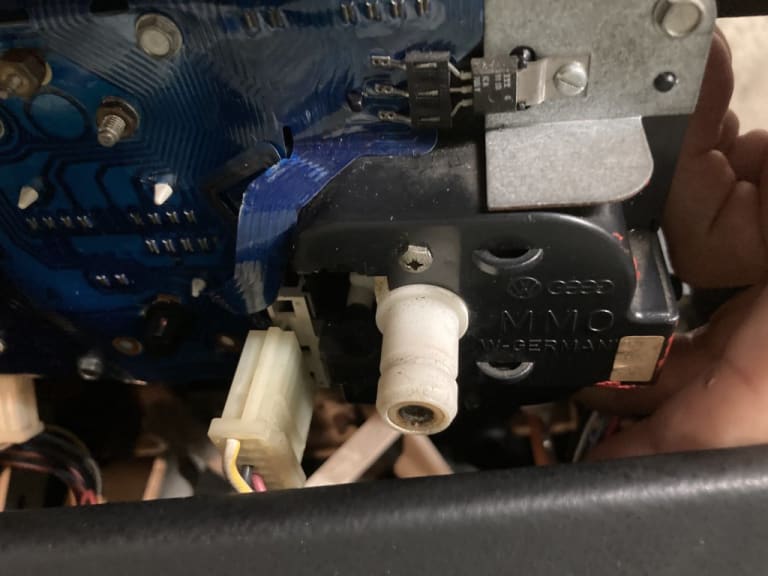
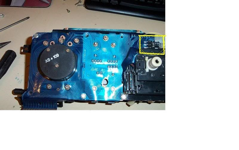
I've also included a picture of the back of my instrument cluster speedo to have someone confirm I do not have the solid state speed sensor. From my "searching knowledge" I don't believe I do.
Steve1973, I am going to run your tests now.
More to come.

Posted
Local Hero

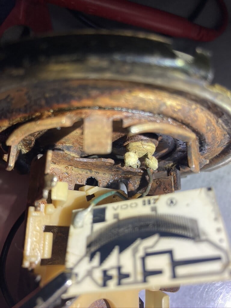
Since you have a good reading to the circuit board then look at the wiring from it to the plug as the plug parts that I am seeing look to be iffy.
You may want to take it as far apart as you can and clean the rust off of it…..as Rust prevents good grounding to the frame as you tighten the thing going back…. But I would resolder all the connections and for that you have to get it a tad further apart. Clean the bend over tabs so they make good contact as rusty crusty parts don't make good connections.
Then use a Micro-clip to test it from the sweep to the pins…. so you know that it is working to the pins.
It appears that you do have a speed sensor, as that is on the left side of the speedo.
Here is some shots of mine from a 92, and 93 mmo clock set.
vdo:
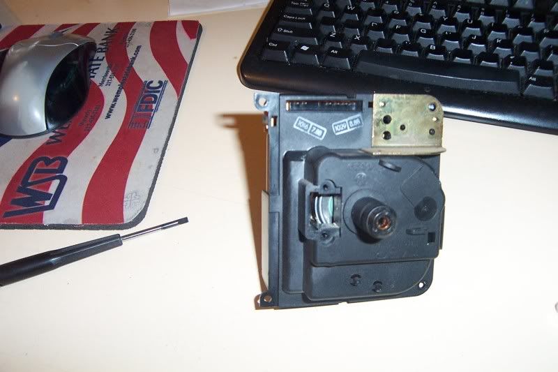
mmo with out:
mmo with:
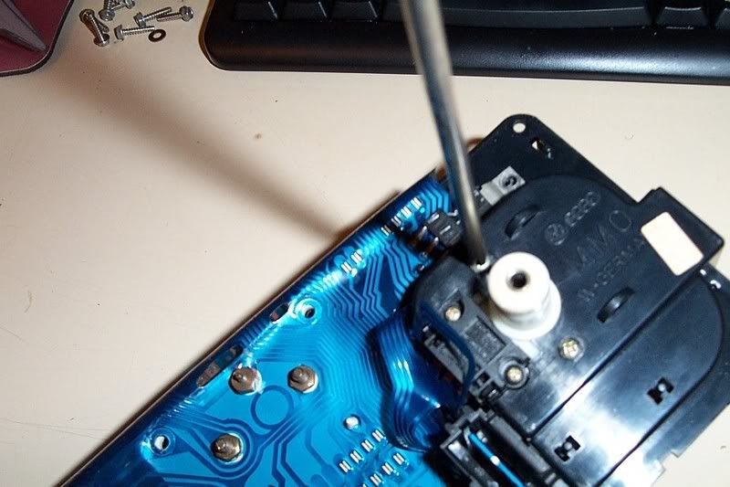
Your wires look cracked and the connections iffy.
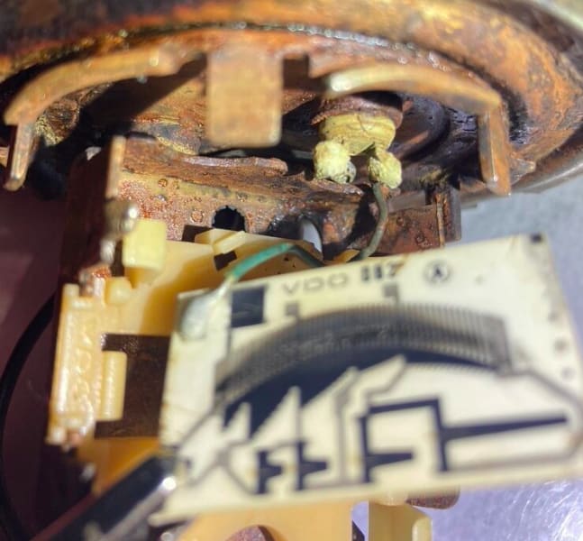
Look at my connections, they are bright and shiny sort of…
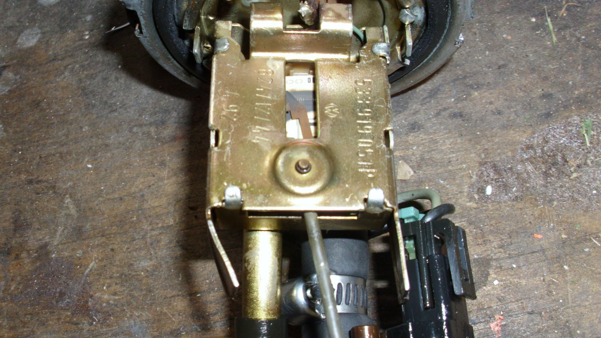
Here is the desoldering tool that I use…..

Try it out, as you add heat to the joint, then while it is hot you such it out. This type won't give you a black eye.
I suggest getting used to the technique so you don't screwup, as it is a heat issue too much and you melt your posts it is heat enough to get the solder fluid, then suck quick…. heat is your enemy…..
 Last edit: by Briano1234
What do Divorces, Great Coffee, and Car Electrics all have in common?
They all start with GOOD Grounds.
Where are my DIY Links?
They all start with GOOD Grounds.
Where are my DIY Links?
Posted
Newbie

YES 1. Check your brown at the sender is grounded with a multimeter (continuity to a known good ground).
YES 2. Check for continuity of the violet/black between the sender and the instrument cluster connector and one of the nuts on the fuel gauge.
YES 3. Check that one side of your fuel gauge(nut on back) has 10v (between nut and good known ground).
However, while checking " Check your ground to the instrument cluster(usually brown)." I could not get continuity, and I frustratingly started over wondering how did I get continuity before. Here is what happened.
When I got 10V at stabilizer, continuity of violet/black, I put a wire on the brown wire ground nut on the gauge and alligator clipped it to good ground. I then tested continuity from sender plug to cluster to fuel gauge nut and it was "good". Plugged in the gauge and it started to work. I removed the patch wire, tested continuity again and nothing. But when I turned the key to on the gauge still worked and moved when I moved the sending unit float.
In short, Fuel Gauge is working but I don't know why. Even as I re-read this I am believing it should not work as I have no continuity tone when I test the brown wire ground on the gauge. Frustrating.
I'm starting to wonder if moving all the parts in the cluster, including jostling the mylar and moving the sender around to do all the testing somehow made it start working. And when I button it all back up, it won't ha ha.
I will do as Briano1234 says and attempt to resolder all those areas to eliminate that and follow-up with this thread if it keeps working or other gremlins creep in.
Posted
Local Hero

For the clusters that I have had issues with I have learned some things.
1. Plump up your connector (Place 1 strip of electrical tape on the pad side of plastic tongue the main mylar connector goes over) to increase tension between the connector and the pins.
2. Add a new earthing point to the Brown wire going to the main connector directly to the Frame….
3. Yes you have probably fixed it with the various tests as you have Scratched clean the earthing issue of the sender as rubbing crusty parts will Scrape clean areas to make a better connection.
4. cleaning the Nuts on the back of the gauges, and the posts (I use 2000 grit sandy paper for the bottoms of the nuts that touch the mylar, and I use an eraser on the mylar, and steel wool for the screw posts) ensures good connectivity. DO NOT over torque the nuts as you can tear the mylar, then you will need to see my how do I back feed 10V stabilized voltages to the cluster thread.
As I said if it is working, Don't go fixing it until it breaks again….
What do Divorces, Great Coffee, and Car Electrics all have in common?
They all start with GOOD Grounds.
Where are my DIY Links?
They all start with GOOD Grounds.
Where are my DIY Links?
Posted
Newbie

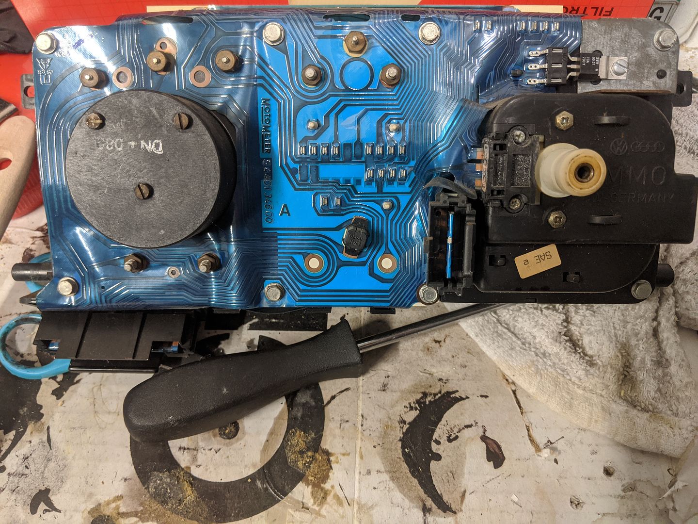
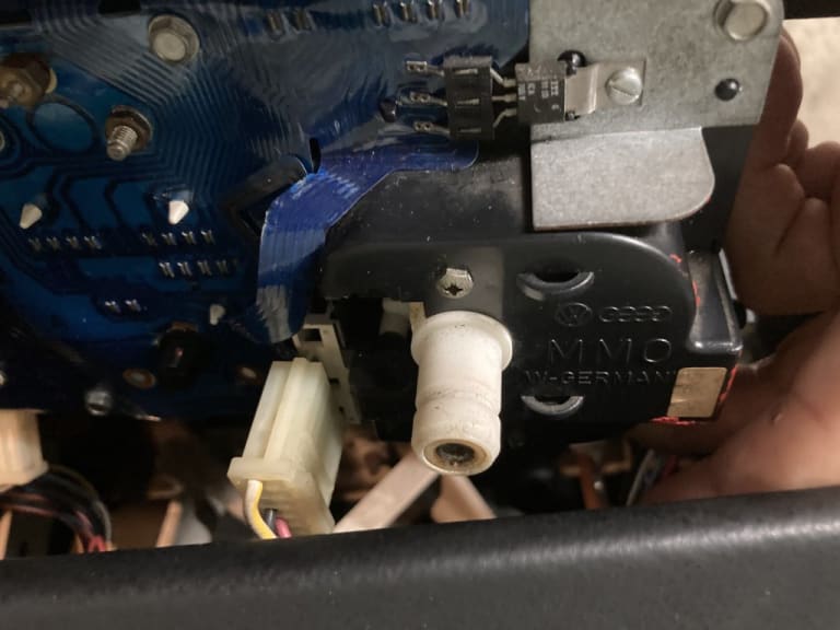
On both of your pictures showing MMO with, there seems to be a cover between the speedometer cable connect and the white plug. Mine does not have that.
As my gauge seems to be working now I understand this may just be knowledge for future troubleshooting.
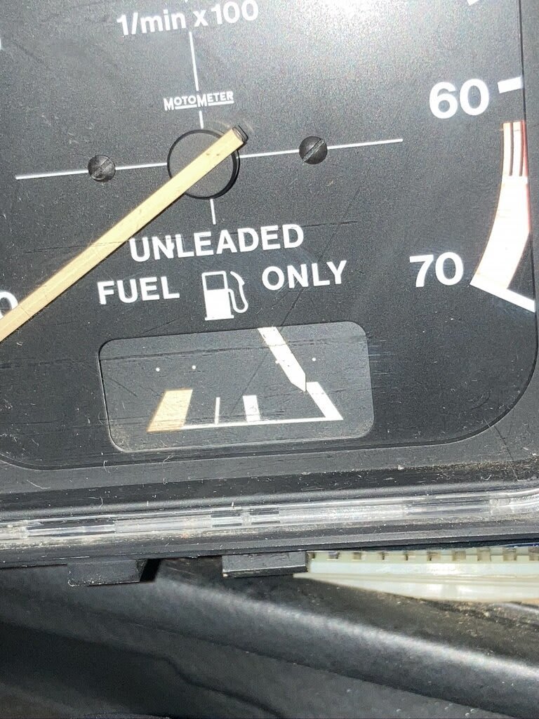
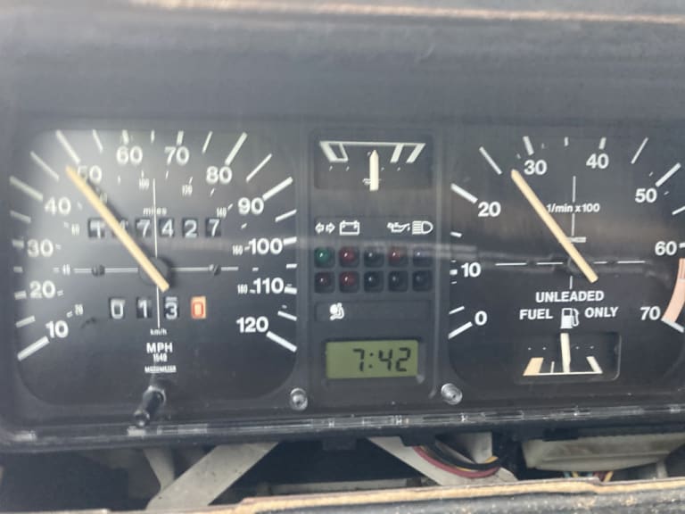
Posting a picture of the "working" gauge with all items plugged in but dash/sending unit not fully installed…hoping it stays that way.
Posted
Settled In

Posted
Local Hero

Steve1973 said
See if this helps, disconnect your battery. Now unplug your instrument cluster. If you look at the connector with the wires, you'll see it un clips. Carefully bend the tangs forward to give more spring tension on the connector. Clean the Mylar contacts with some sort of contact cleaner.
Don't use any contact cleaner or electrical cleaner… the age of the mylar and the cleaners will dissolve the bonding between the mylar ……and you will be up ca-ca creek with no paddle or Kayak. I would say Canoe but that is a US thing.
If you use the Plump technique you won't hurt a thing or break a pin.
What do Divorces, Great Coffee, and Car Electrics all have in common?
They all start with GOOD Grounds.
Where are my DIY Links?
They all start with GOOD Grounds.
Where are my DIY Links?
Posted
Newbie

I will, and so glad you concur, leave it be until it "breaks" again and hopefully by then I will be ready to perform surgery on the solder joints…that's intimidating for me on a part that seems challenging to get here in the US second hand market. Yet I have to get over that and take the dive some day.
Prior to proper reinstallation I will plump technique as well as examine and clean (with appropriate cleaner) the mylar, nuts and posts as mentioned.
Again, thank you both for your time, understanding and clear guidance and terms to get me this far.
I'm certain I will post again and should I find anything I do helpful to the community ensure I post it for review and inclusion as reciprocation for the wealth of knowledge for what is now a new adventure for me.
Kind regards,
Ken
Posted
Settled In

Briano, you are correct but it depends on the experience of the person doing it. I have done it a few times on different cars without issue. Note I used the word "carefully'. Also I should of been clearer with the contact cleaner. I spray I small amount onto some tissue or ear bud until it's just damp and give it a quick clean.Briano1234 said
Don't use any contact cleaner or electrical cleaner… the age of the mylar and the cleaners will dissolve the bonding between the mylar ……and you will be up ca-ca creek with no paddle or Kayak. I would say Canoe but that is a US thing.Steve1973 said
See if this helps, disconnect your battery. Now unplug your instrument cluster. If you look at the connector with the wires, you'll see it un clips. Carefully bend the tangs forward to give more spring tension on the connector. Clean the Mylar contacts with some sort of contact cleaner.
If you use the Plump technique you won't hurt a thing or break a pin.
 Last edit: by Steve1973
Posted
Newbie

Thank you all and I look forward to more successful ventures!!!
Have a good weekend.
Posted
Local Hero

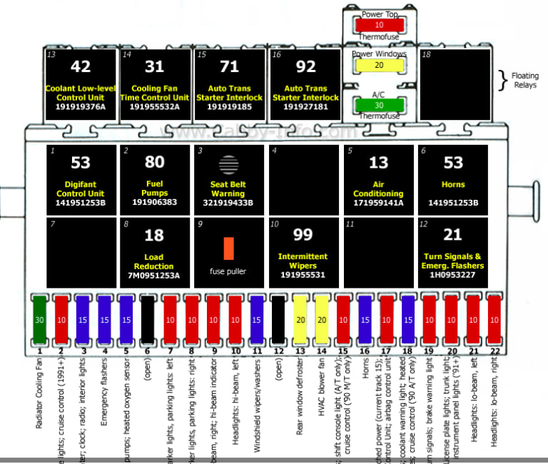
The Fasten seat belts can be the switch in the Seat belt receiver not being plugged in or the bulb is out in the thing but, the other thing I found is that it is the only plug in the dash that can be placed on upside down, and you don't know it until it don't work.
So if you had the dash in and out, remember on the Brake light that the pins go on the pad side of the connector.
If they have by-passed the "la-coocarocha" warning relay with a jumper that is also an issue…. it is the only relay with a speaker grille on it.
What do Divorces, Great Coffee, and Car Electrics all have in common?
They all start with GOOD Grounds.
Where are my DIY Links?
They all start with GOOD Grounds.
Where are my DIY Links?
Posted
Local Hero

https://www.youtube.com/watch?v=XtpL630kIzw
Posted
Settling In

Posted
Local Hero

DaveFMk1 said
Hi All just seen this chat and want to jump aboard as I have a broken fuel sender unit and need a replacement but not sure if etiquette says I am permitted - thanks
etiquette is drinking tea with your pinky raised.
We are grease Monkeys with Gloves….
If your sender is broken it depends on how it is broken to get a fix.
IIRC there was a thread on here where the POLO sender can be used, the only thing different is that the POLO connector is straight up, and not at a 90 degree to the unit.
What do Divorces, Great Coffee, and Car Electrics all have in common?
They all start with GOOD Grounds.
Where are my DIY Links?
They all start with GOOD Grounds.
Where are my DIY Links?
0 guests and 0 members have just viewed this: None.


