


Moredoor 24V VR6 4Motion Turbo (Project BahnStorm)

Posted

Settled In

Yes, I'm pretty much as insane as that sounds!
That didn't stop me buying my turbo though! A Compressor Racing RS-341, which is an HY35/HX35 hybrid, giving huge airflow from 3000rpm to the VR6 red line, a perfect power band for my needs and solid reliability from the Holset core.


I also picked up the forged rods and pistons, along with a manifold chucked in for free. The manifold may not fit, but I'm not building the engine until the main fabrication work is complete.


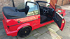
That was months ago, but now i finally have some progress! I was going to be taking it to TSR performance round about now, but they had to re book for march next year, and I can't wait that long! So, she is now going to BHP (Brand Hatch Performance) to have the 4Motion, EPAS and probably a few other bits fabricated in by my bosses friend! With that news, last weekend me and team of minions set to stripping her down, first ripped the tank out (what a t*** that is) and most of the engine bay components, and then moved her onto the drive. Then the dash, loom, seats, trims, carpets and any other bits and bobs! I will let the pictures speak, but for �500, I'm very pleased with how damn solid she really is!


Not much left to take out now, and off to the fabricators for a make over!
Posted
Settled In
Annoyingly i rushed the glass and put too much pressure on one side and it cracked….so i shall use that as an excuse to get a heated one!


picture hosting
All of the remaining large parts are off!

adult image sharing
The Webasto came out with no issues and is in really very good condition, shouldn't take much to get it back to how it should be!

how to capture screen
The rest of the shell is still in fantastic condition, around the windscreen there is NO rust and even the roof is only minor surface rust!

pc screenshot

windows 7 print screen

upload pictures free

image sharing
She's also been taken down to BHP for the work to start in the new year!

online photo storage
Just need to drill the rear door bolts off and tear out the brakes and suspension!
Bring it on!
Posted
Settled In

image hosting site

imgur
Beam and Haldex have been dropped off, she's sharing space with some valuable motors!

Settled In
First dropping the front suspension, followed by the beam…


Then the rear doors (nightmare)…


Followed by the steering rack and pedal box/column…


Shortly followed by chopping the spare wheel well out to make way for the Haldex.


Tomorrow we'll get it up on the spit so we can flip her upside down for fitting the rear beam!
Settled In

Steel beams used to adapt the A frames to fit the Golf, first bolted to the car, long beam laid on top and tacked into place, then removed and properly welded together!


The result! (She clearly didn't fall off the front of the jig when we lifted the back up…definitely not!)

Found a little bit of a hole, not too bad though, will be welding around here anyway later on!

Where the previous owner ran her so low, she scraped and put a hole on the floor, that will need to be fixed!

Overall the floor pan isn't bad!

The remains of the wheel well still firmly welded to the massive beam that runs along the width of the car to brace and create a strong mounting area for the seat belts…they went to town welding those on didn't they!

Here are the two mounts for the original rear beam, rotten around the rear sill area, and the O/S had been welded before. But, the new rear beam actually has to be mounted slap bang in the center of those two bolts, so it will need to be chopped out and a mount surface re fabricated anyway! The width is perfect for it!


After offering up the beam it's clear that the boot floor will have to be raised anyway; regardless of fuel tank position, just to get the rear of the beam high enough to get the Haldex level and at the correct height! So, chop out what we need!

Those belt mounts weren't going anywhere!

Good job he can read that….

Posted

Moderator


Making a great start though
Posted
Settled In

Posted
Settled In
Got the rear arch liners out to have a good look at the filler neck and seat belt mount rot, could be worse, still needs sorting though!

image hosting 5mb
The beam was then offered up and a pan was made on where to go from here. As you can see the beam lies pretty much slap bang in between the two original mounting studs!

jpg images

image upload no limit

adult photo sharing
Next we made the templates for the water cutters. This one being the main mounting surface for the beam:

img upload
This one for gong over the top of the beam so both halves of the mount are supported:

images upload
Once back from the cutters they were bolted to the beam and offered up.

photoupload

img host
Then, after marking it out, the chopping began!

screencast
Some lovely repairs here! A plate over the rot with a lovely chicken s**t welding and bathroom sealant!

pic host

image upload
During and after! Scary stuff, can't go back now!

picture uploader

temporary image hosting
We then had to relieve the sill with heat, a round block of ally and a hammer to make just a little more room!

free upload
The end result…not bad!

gif image hosting
We then got annoyed with constantly putting e beam in and out so we flipper her…never done this before, how weird!

image url
The next few images are the beam located in its intended position, roughly. The back end needs to go up into the boot a further 2.5-3 inches, and the front another inch. The wheels are actually at a good height, however because of the angle of the beam, it has put excess camber and toe on the wheel. Raising the back of the beam should give some back, and overall raising of it should lower the arms a bit more. Any final tweeks can be done on the mounting points of the arms on the beam its self. Next door have the most up-to-date 4 wheel laser alignment rig, how handy is that?! The Rear chassis rail also needs to be re-engineered as the arms hit it already, so I have no travel, and the driveshafts also struggle with going through steel!

photo uploading websites

image hosting without registration

screengrab

photo upload
Next on the list is to fit the rear seat and see what height the seats lie when flat, then we can raise the boot floor to the same height for a cleaner look. The beam can then be put in it's final position for mounting! After that the chassis rail mods can go ahead! Some tiny 10 inch coilovers will also need to be made to compensate for the higher mounting position on the Rallye beam!
Posted
Settled In
The beam is IN!
I went up to the workshop to drop my rear seats off for measuring, turns out it was a waste of time, I'll get to that later! But, i did notice some work had been done! A whacking great big girder had been tacked into place and joined to two mounting pates! Oh and a load more boot had been chopped out, who needs that anyway?!

image hosting over 5mb

image url

image hosting over 2mb
I couldn't ask what was happening as Clint had popped out, so I left it and returned on Saturday…the girder had been taken out and the rough mounts visible, it was so close to fitting!

free upload image

image hosting 10mb limit
Next weekend was even better! Beam mounts made and welded in with captive nuts for main bolt and top plate.

screen capture

img hosting
So we then chopped out what metal was still in the way and bolted her up! She fits! (Guess most things would after removing a lot of car first). The beam only intrudes into the boot a little bit…honest

image hosting
So we put the trailing arms on with a wheel and the results… with the beam an inch higher and the back end up where it should be, the toe-in and camber…gone! Wheel sits bang on!

image host

adult image

picture share
And of course we had to test fit the diff…uuuuuurm. Well that needs modifying doesn't it! It would be fine if i didn't want to use the back seats, tunnel it and job done. But because I'm a pain, I do want to use them do the diff needs to be lowered to clear the seats. This also means a smaller tunnel, if any at all. We got all flustered about the driveshaft angles and the fact that they sit forward of the hub at an angle, until we worked out that they are like this standard and it's a CV joint, so it doesn't matter at all!

images upload
Posted
Settled In
Keep the updates coming
Posted
Settled In
 She just doesn't look very pretty right now…at all!
Posted
Old Timer

Posted
Settled In
Nah, it's all covered above
Posted
Settled In
I got the wings off! Why were the bolted?! Enough of that horrible underseal stuff to keep them on for a life time!

imgur
Next on the list was building up a new chassis rail to make way for the trailing arms and drive shafts. First off grind back the old beam so it's nice and flat!

image hosting without registration
Then measure the required distance of the sheet metal, and make a car template.

host image online
Next the cut out sheet was paced at the start and tacked in place, it was then man handled into place and tacked in small amounts to make sure it went on flat. The idea here is to basically build another box-section rail above the existing one. So this metal sheet will follow the right shape, it will then be welded along the top of the original rail, and a shelf will then be made from that to the arch/body. Effectively making an "8" shape if you look from the rear of the car, with the new rail right above the old.

pic host

image hosting services

imgurl
Welding along the top edge.

pic upload
The next part I can't show you…because i turned up and this incredible fabrication was already done!

image posting

greenshot

image sharing sites
Next we fitted the seat to see what had to be removed to make way for it, luckily not that much! Just a trim ant it will go right back in.

upload image online

screen capture tool
Next will be a main cross member which will also double as the rear hanger for the diff/beam. Then a smaller cross member just behind/under the seat for the seat belt mounts to go on. Then the boot floor! Hopefully we can sit her on her back wheels soon and then start work fitting the VR!

Settled In
 good work brother

Settled In
Well done, can't wait to see this progress.
0 guests and 0 members have just viewed this: None.