"TAG" - 1983 Campaign restoration blog
Posted
Old Timer


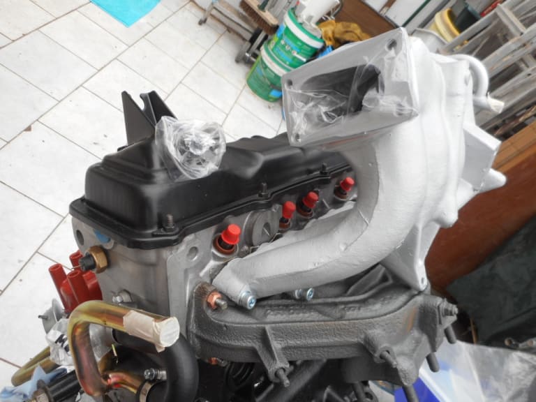
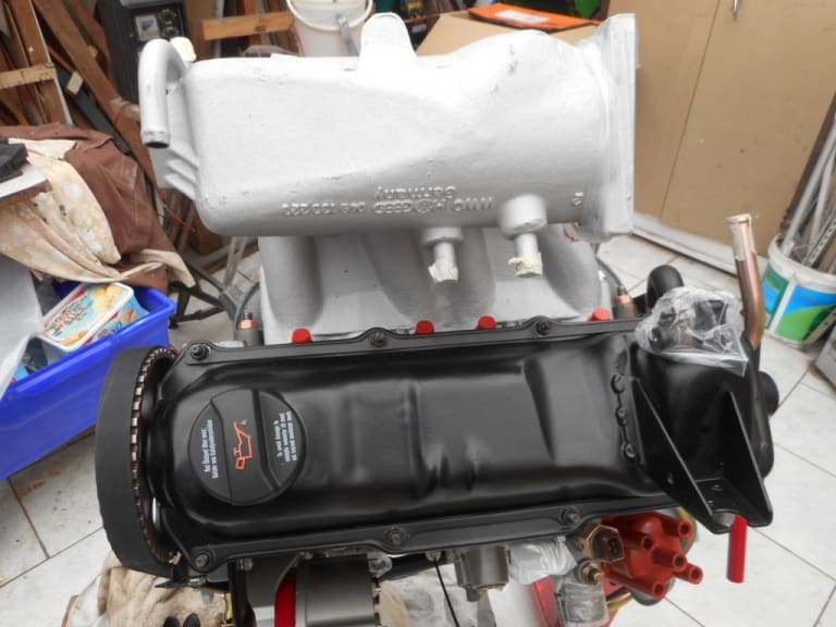
1983 Golf GTi Campaign Edition, Diamond Silver
http://vwgolfmk1.org.uk/forum/index.php?page=topicview&id=projects%2Fyour-mk1-golfs_2%2F-tag-1983-campaign&redirected=1#post_1551531
http://vwgolfmk1.org.uk/forum/index.php?page=topicview&id=projects%2Fyour-mk1-golfs_2%2F-tag-1983-campaign&redirected=1#post_1551531
Posted
Old Timer
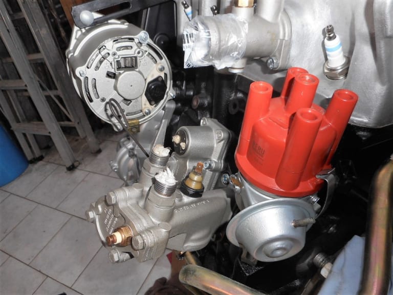
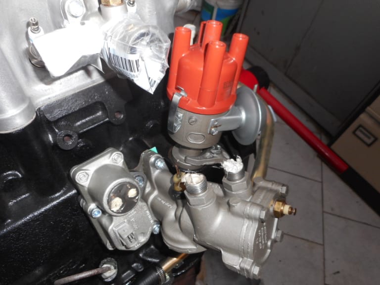
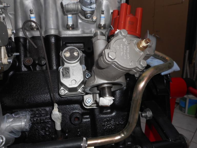


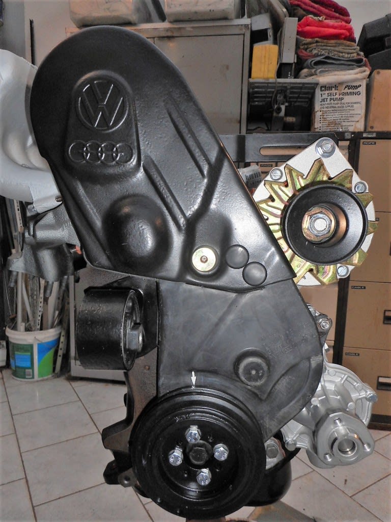
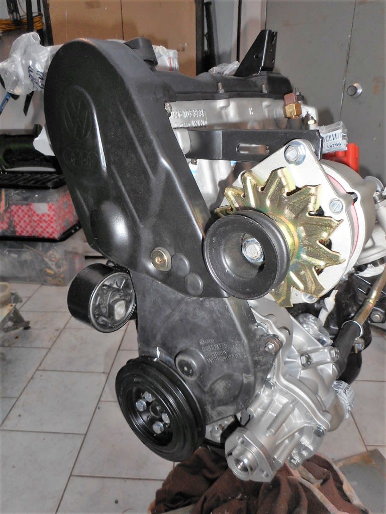
I have changed the socket-headed bolts that gave such trouble to remove with hex head bolts.
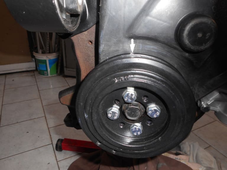
1983 Golf GTi Campaign Edition, Diamond Silver
http://vwgolfmk1.org.uk/forum/index.php?page=topicview&id=projects%2Fyour-mk1-golfs_2%2F-tag-1983-campaign&redirected=1#post_1551531
http://vwgolfmk1.org.uk/forum/index.php?page=topicview&id=projects%2Fyour-mk1-golfs_2%2F-tag-1983-campaign&redirected=1#post_1551531
Posted
Old Timer
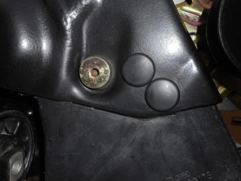


I shall post in the help section.
1983 Golf GTi Campaign Edition, Diamond Silver
http://vwgolfmk1.org.uk/forum/index.php?page=topicview&id=projects%2Fyour-mk1-golfs_2%2F-tag-1983-campaign&redirected=1#post_1551531
http://vwgolfmk1.org.uk/forum/index.php?page=topicview&id=projects%2Fyour-mk1-golfs_2%2F-tag-1983-campaign&redirected=1#post_1551531
Posted
Old Timer


"TAG" - 1983 Campaign restoration blog
cdgthreesalmons said
The hit a snag with the water pump pulley catching on the plastic cam belt cover!?!?!?
I shall post in the help section.
Mine does it ever so slightly. I replaced the pulley thinking it would solve it but new pulley was no different. Been like it at least 3 years now.
Sent from my iPhone using Tapatalk
Mars red 1.8 GTI tintop now MOT'd and on the road!
http://vwgolfmk1.org.uk/forum/index.php?page=topicview&id=projects%2Fyour-mk1-golfs_2%2Fwent-to-look-at-a-golf&kfs79=150
http://vwgolfmk1.org.uk/forum/index.php?page=topicview&id=projects%2Fyour-mk1-golfs_2%2Fwent-to-look-at-a-golf&kfs79=150
Posted
Old Timer


Posted
Old Timer


1983 Golf GTi Campaign Edition, Diamond Silver
http://vwgolfmk1.org.uk/forum/index.php?page=topicview&id=projects%2Fyour-mk1-golfs_2%2F-tag-1983-campaign&redirected=1#post_1551531
http://vwgolfmk1.org.uk/forum/index.php?page=topicview&id=projects%2Fyour-mk1-golfs_2%2F-tag-1983-campaign&redirected=1#post_1551531
Posted
Old Timer


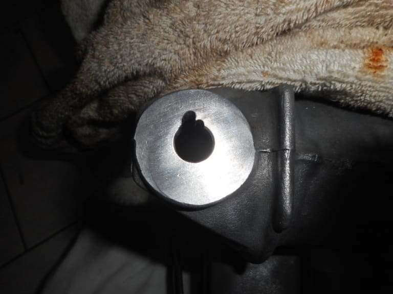
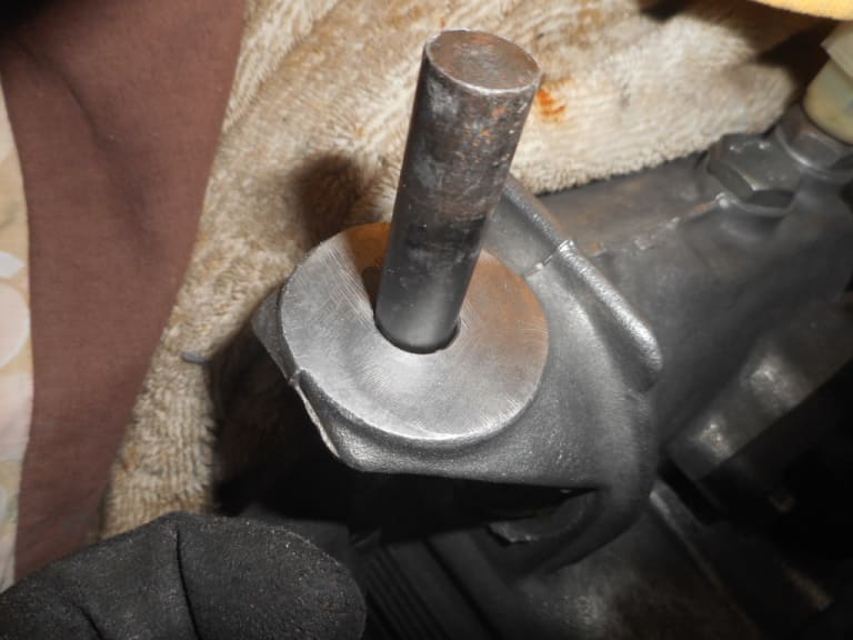
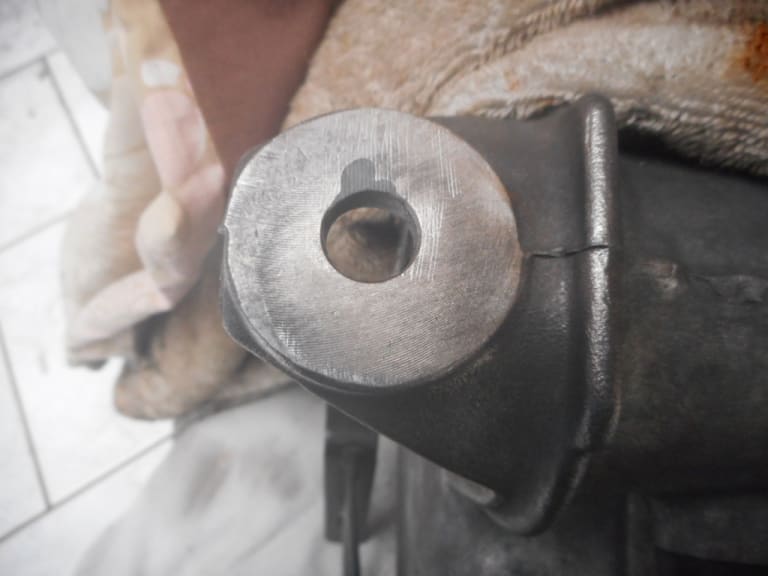
I bought some alloy metal repair - like Plasticine, you kneed it in your fingers till warm - then having cleaned the hold thoroughly and degreased it - I used an old drill bit of the correct diameter - packed in the repair paste before filing it flat the following morning. Seems to have worked well - time will tell. But with the correct rubber clutch cable guide fitted it will hopefully last.
1983 Golf GTi Campaign Edition, Diamond Silver
http://vwgolfmk1.org.uk/forum/index.php?page=topicview&id=projects%2Fyour-mk1-golfs_2%2F-tag-1983-campaign&redirected=1#post_1551531
http://vwgolfmk1.org.uk/forum/index.php?page=topicview&id=projects%2Fyour-mk1-golfs_2%2F-tag-1983-campaign&redirected=1#post_1551531
Posted
Old Timer


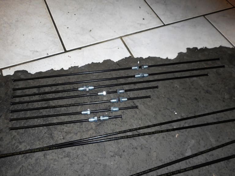
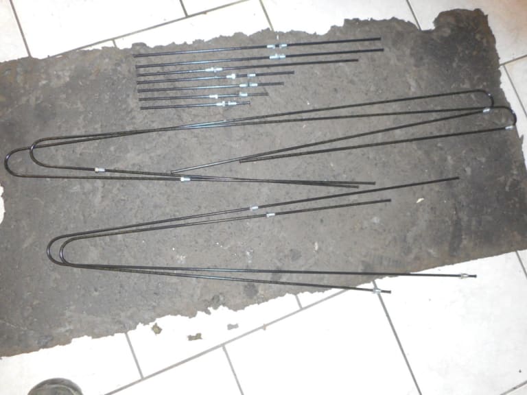
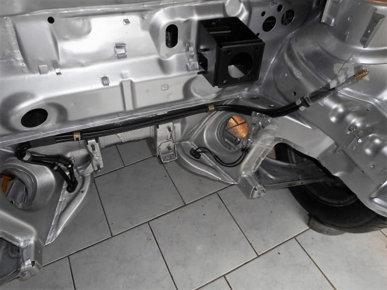
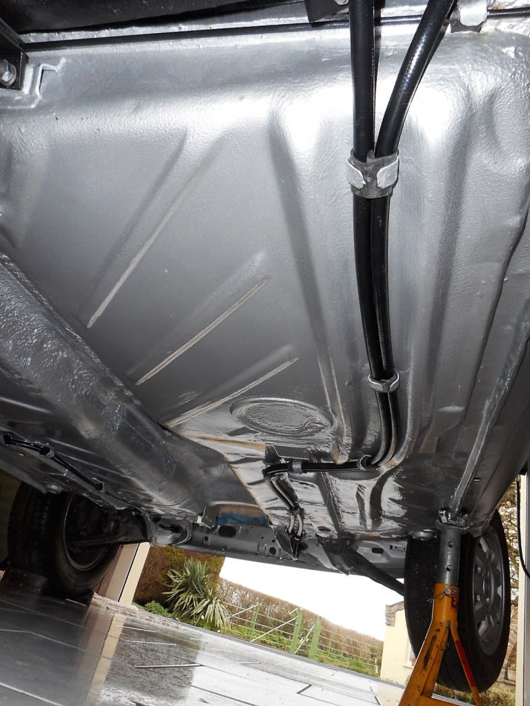
Bending them to shape proved surprisingly easy. I used the old pipes as a template and cable tied the new/old together as I went along to form the more complex shapes. I started with the easir pipes at the rear of the car.
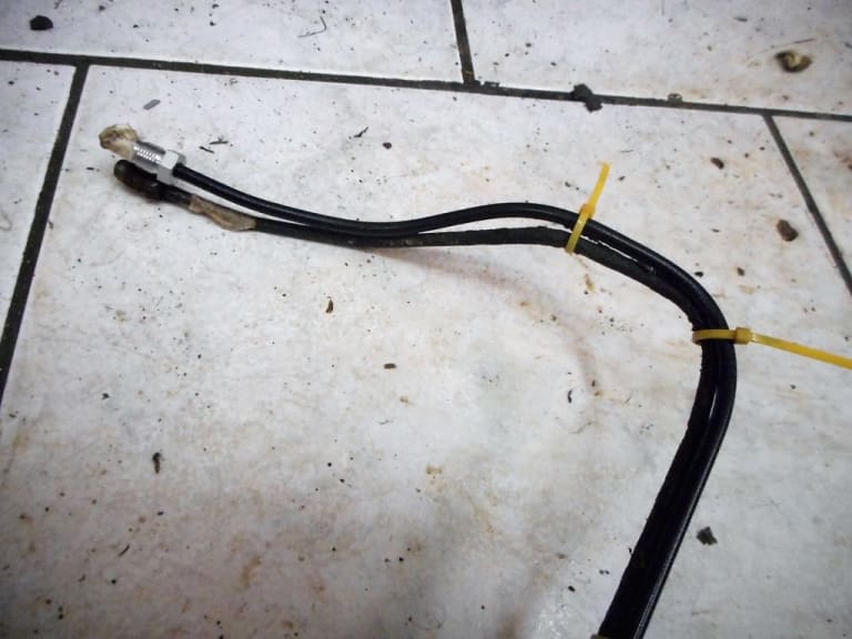
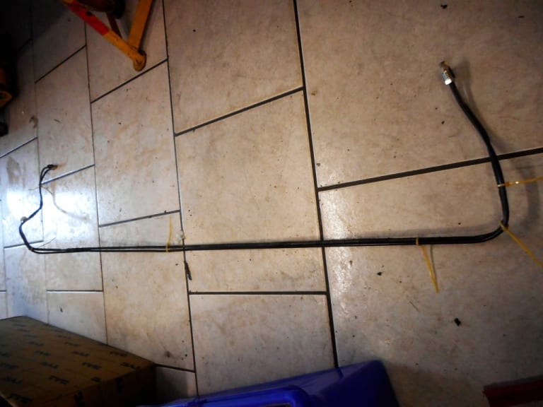
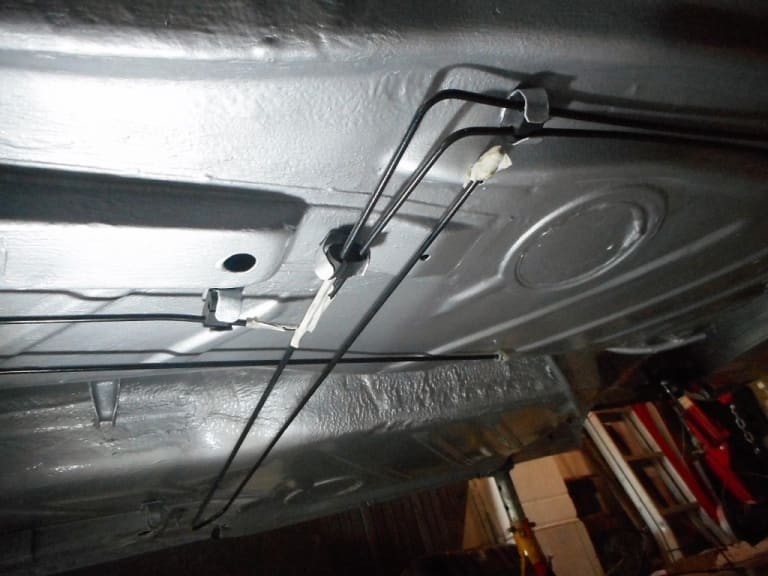
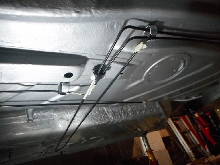
This wasn't possible for the two front-back pipes due to their length, and due to getting them through the grommet in the engine bay. I found I could pre bend the rear section, and the middle "S" bend before feeding the remaining straight section through the grommet - then bending that section to shape. Quite tricky getting the bends right through that tight bend by the grommet.
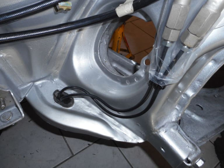
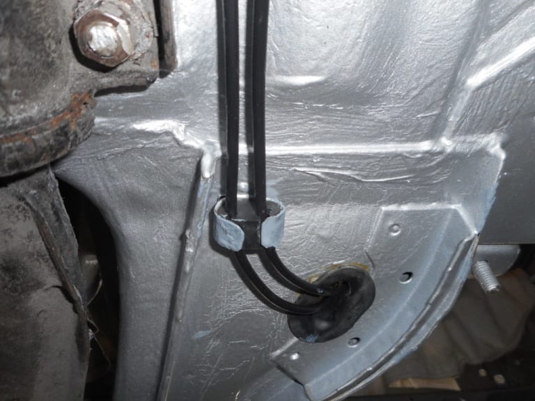
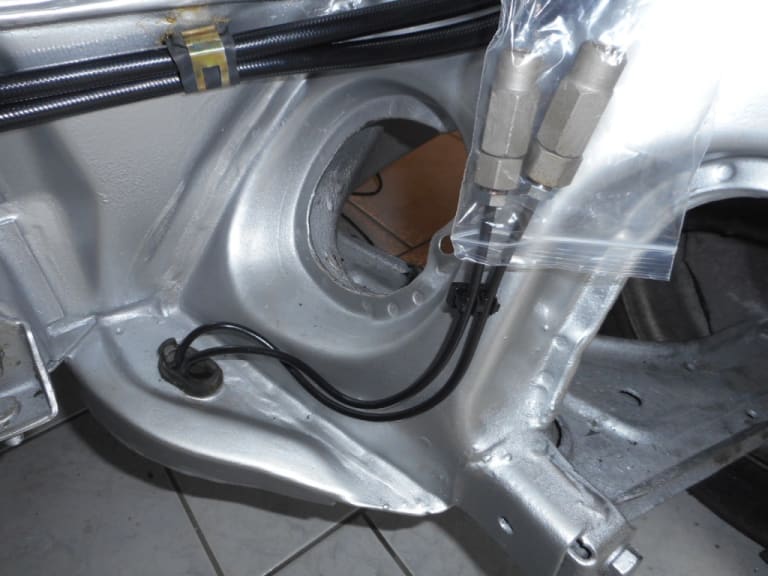
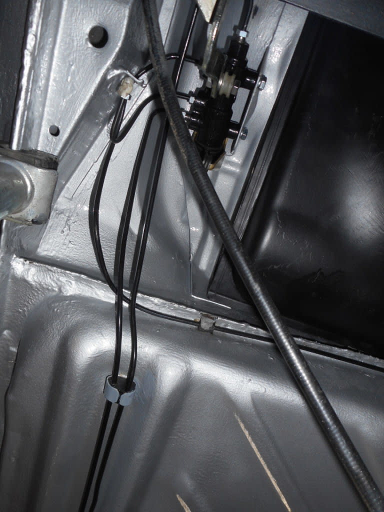
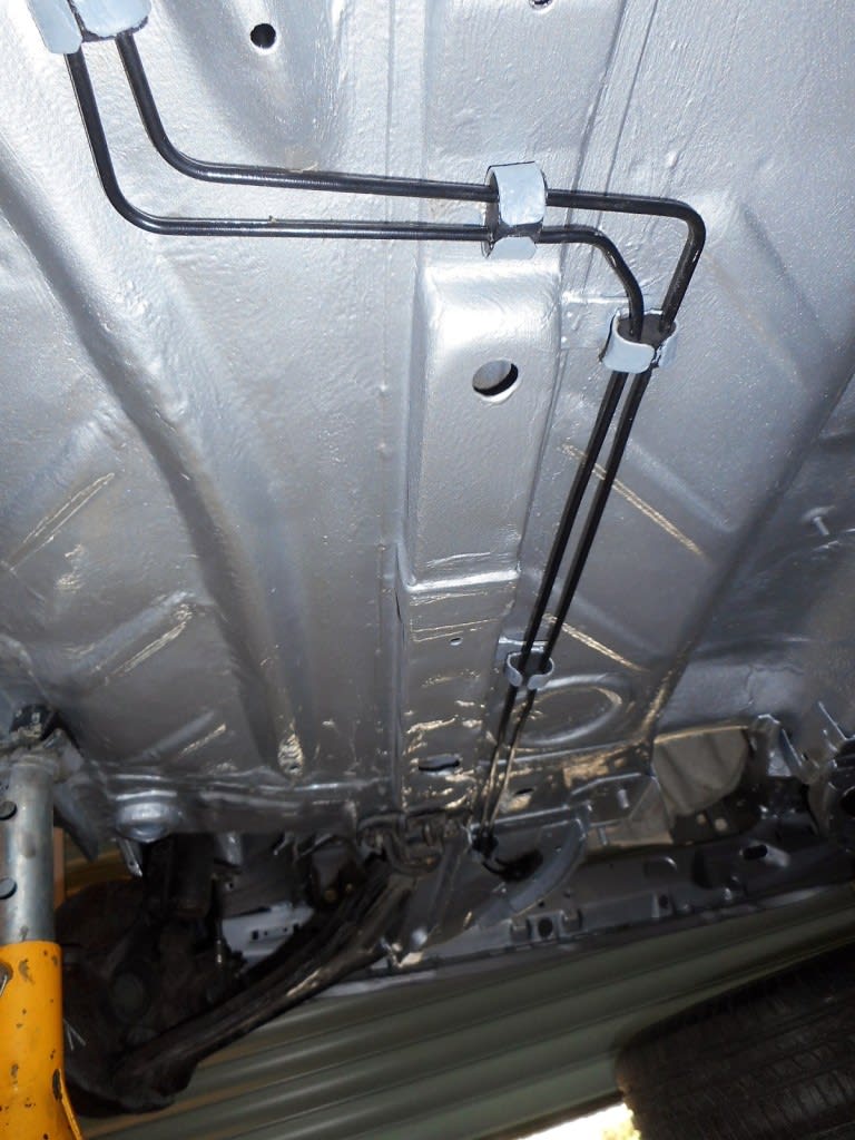
Rather pleased with them.
1983 Golf GTi Campaign Edition, Diamond Silver
http://vwgolfmk1.org.uk/forum/index.php?page=topicview&id=projects%2Fyour-mk1-golfs_2%2F-tag-1983-campaign&redirected=1#post_1551531
http://vwgolfmk1.org.uk/forum/index.php?page=topicview&id=projects%2Fyour-mk1-golfs_2%2F-tag-1983-campaign&redirected=1#post_1551531
Posted
Old Timer


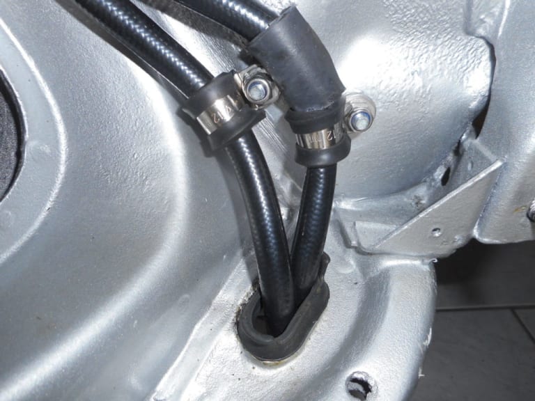
Again mine were damaged on removal so time for some new ones. I bought a set of flexi pipes from ClassicVW. Again a great item. I decided against the braided pipes and instead went for black plastic coated pipes. I thought these would have less tendency to hold onto water/dirt than the rougher braided finish.
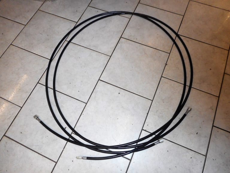
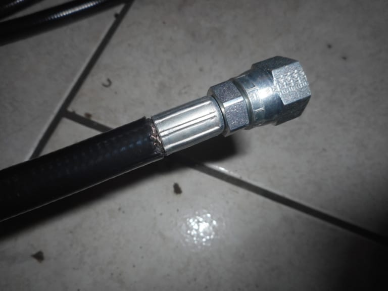
Fitting them proved to be a bit of a nightmare!! The issue is that they are hard to bend into a tight radius. unlike the original steel pipes which had very tight bends in them - it proved impossible to achieve the same with the flexis- a bit like trying to bend stiff garden hose into tight bends. The pipe would bend so far but there was a fear of "kinking" them. This meant that over the length of the pipe run I ended up with an excess of flexi! I think they could have been manufactured shorter than the steel originals to take account of this. Clearly each end has a fairly fixed location - connecting to the meter head pipes one end - and the tank/accumulator at the other.
I wonder if anyone else has found the same. In fact there was so much excess I could almost connect straight into the accumulator with out the braided flexi connector hose.
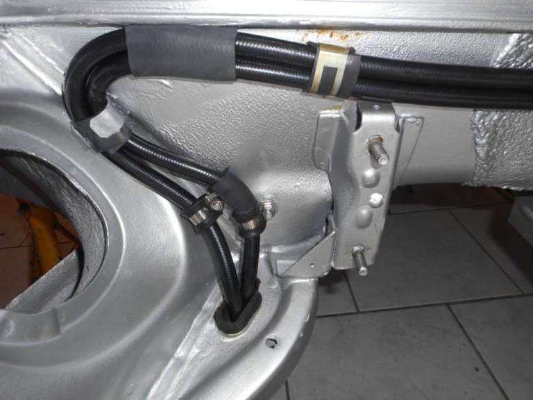
In the end I managed to "loose" most of the excess in the engine compartment by taking a longer route across the bulkhead.
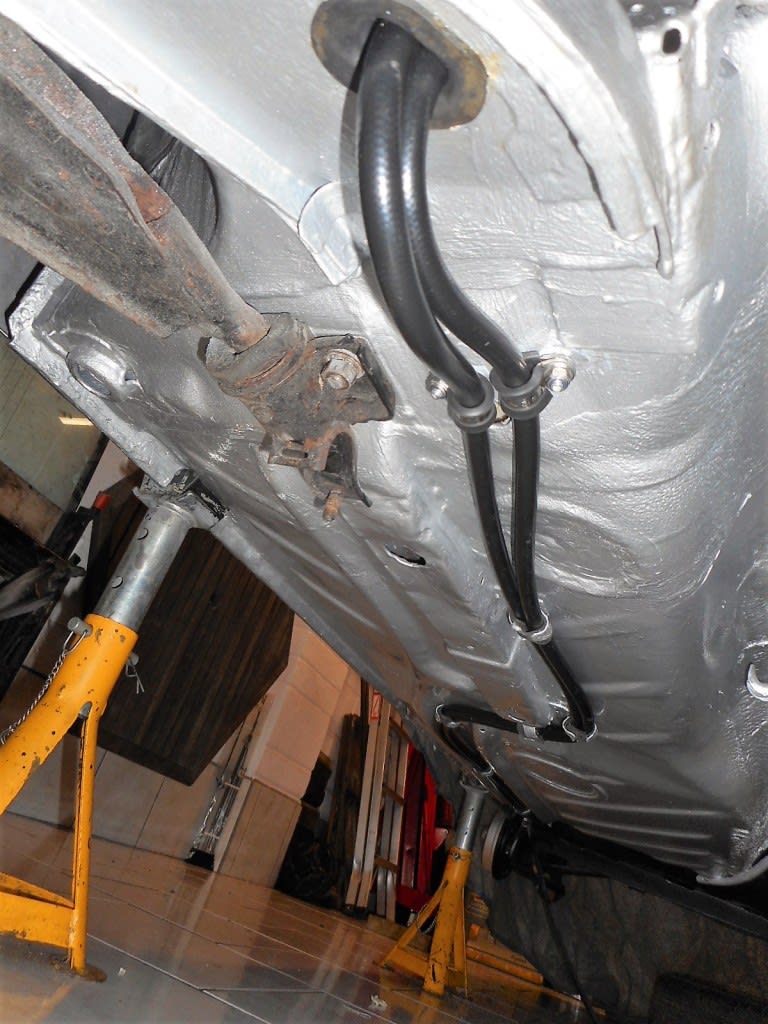
It was also impossible to bend the pipe, and keep it place due to it's flexi nature, on the very tight bends through the grommet where they enter the engine compartment. Trial fitting the steering rack found they were catching the steering rubber bellows. I have seen other cars fitted like this - not good for the longevity of the bellows!
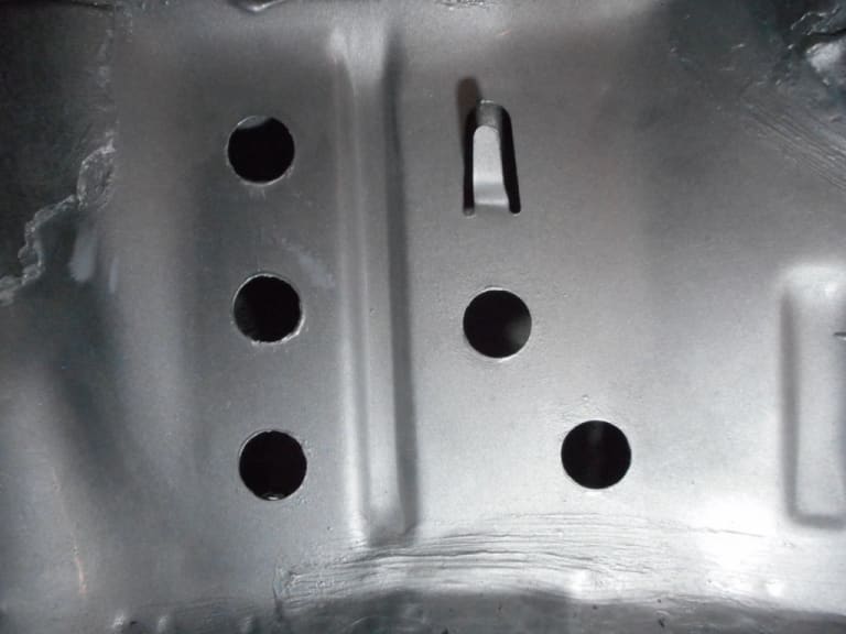
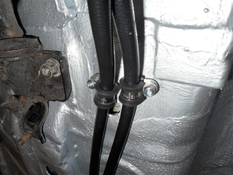
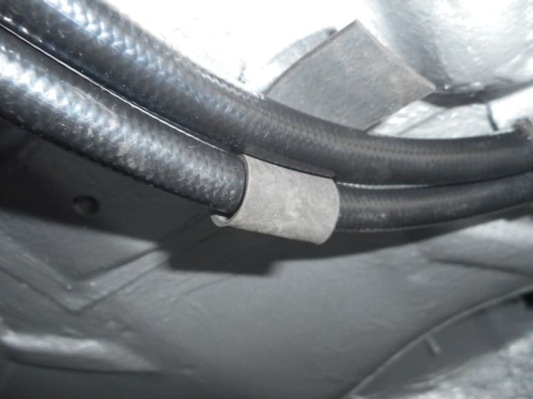
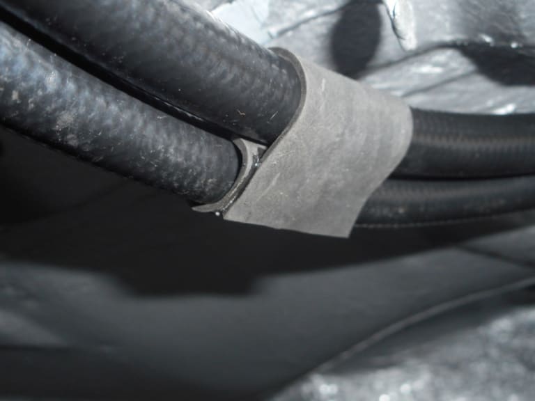
In the end I decided to fit "P" clips. I drilled though the body. Sods Law - the holes were in the double thickness under drivers side foot panel - near the pedals. I could just access this through the holes in the panel. I fitted two M6 stainless bolts through the holes, having rust proofed the holes first and added seam sealant as they passed through. I could then lock them in place with a nut on the outside. After applying further seam sealer in/out I could then fit the "p" clip with a nyloc stainless nut. Worked very well and pretty neat.
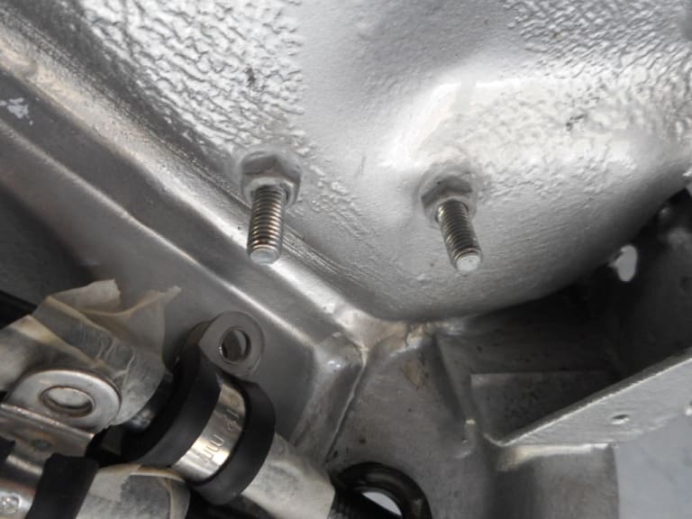
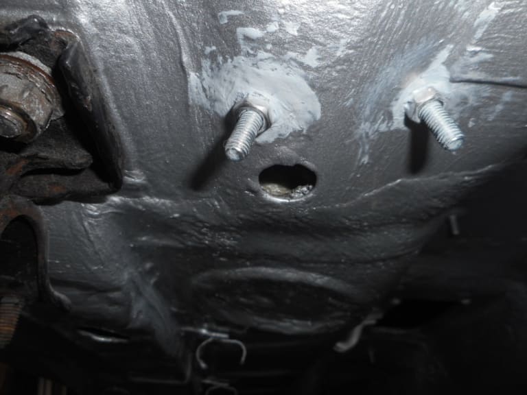
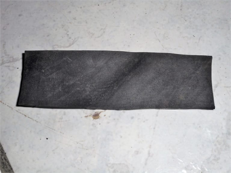
Finally - the rubbers that held the old steel fuel pipes were too small to hold the new flexis. I therefore cut strips of old rubber inner tube and wrapped the pipes in those- making sure there was rubber between the pipe to stop chaffing. I super glued the end of the rubber to itself. Inevitably re-shaping the metal tabs to accept the new pipes meant "grizzling" them rather with the pliers so I repainted those in silver Hammerite afterwards. Great thing about a Diamond Silver car - silver Hammerite is an almost exact match!
1983 Golf GTi Campaign Edition, Diamond Silver
http://vwgolfmk1.org.uk/forum/index.php?page=topicview&id=projects%2Fyour-mk1-golfs_2%2F-tag-1983-campaign&redirected=1#post_1551531
http://vwgolfmk1.org.uk/forum/index.php?page=topicview&id=projects%2Fyour-mk1-golfs_2%2F-tag-1983-campaign&redirected=1#post_1551531
Posted
Old Timer


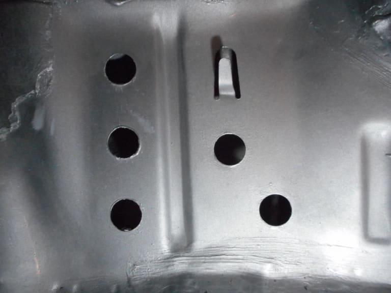
Access to fit the bolts - tricky!!!!!
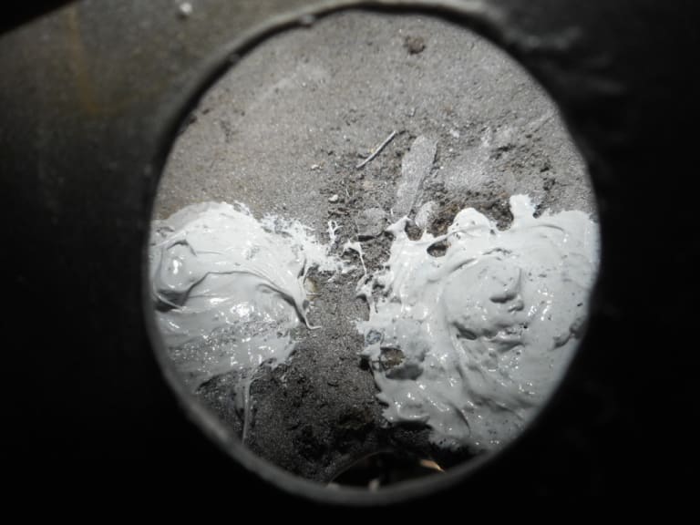
Bolts fitted and seam sealed
1983 Golf GTi Campaign Edition, Diamond Silver
http://vwgolfmk1.org.uk/forum/index.php?page=topicview&id=projects%2Fyour-mk1-golfs_2%2F-tag-1983-campaign&redirected=1#post_1551531
http://vwgolfmk1.org.uk/forum/index.php?page=topicview&id=projects%2Fyour-mk1-golfs_2%2F-tag-1983-campaign&redirected=1#post_1551531
Posted
Old Timer
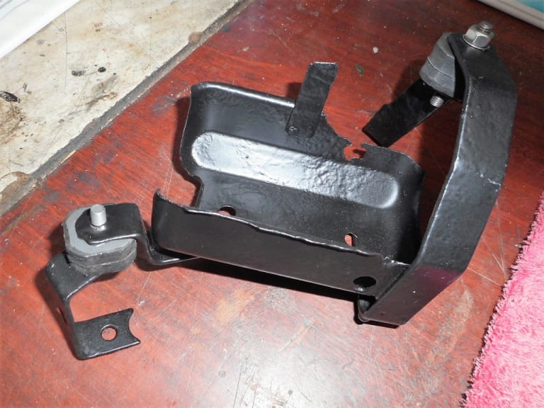
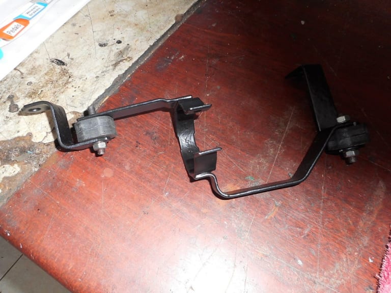
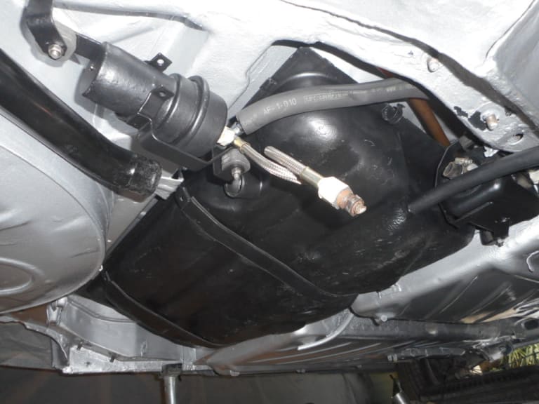
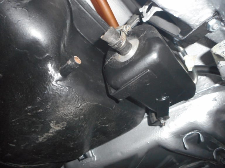


The end of pretty busy week!!!
1983 Golf GTi Campaign Edition, Diamond Silver
http://vwgolfmk1.org.uk/forum/index.php?page=topicview&id=projects%2Fyour-mk1-golfs_2%2F-tag-1983-campaign&redirected=1#post_1551531
http://vwgolfmk1.org.uk/forum/index.php?page=topicview&id=projects%2Fyour-mk1-golfs_2%2F-tag-1983-campaign&redirected=1#post_1551531
Posted
Old Timer


"TAG" - 1983 Campaign restoration blog
Sent from my H3113 using Tapatalk
Posted
Old Timer


Posted
Old Timer


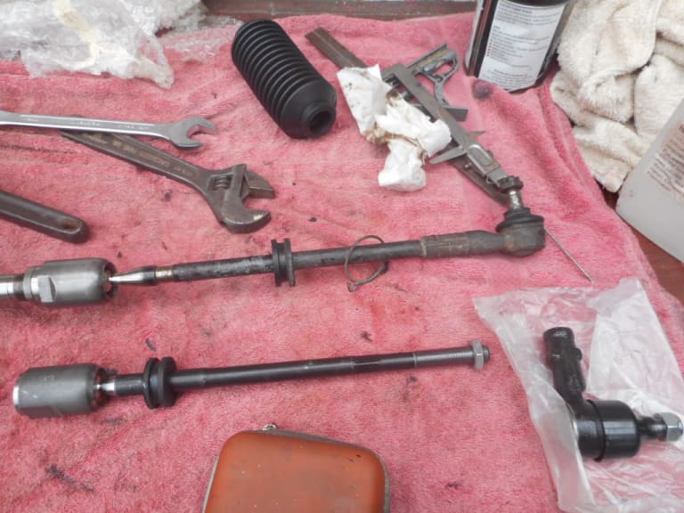
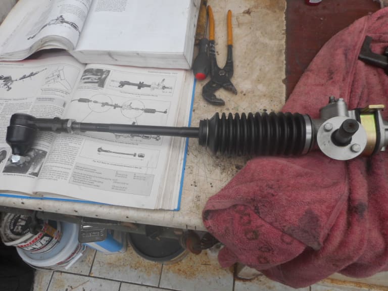
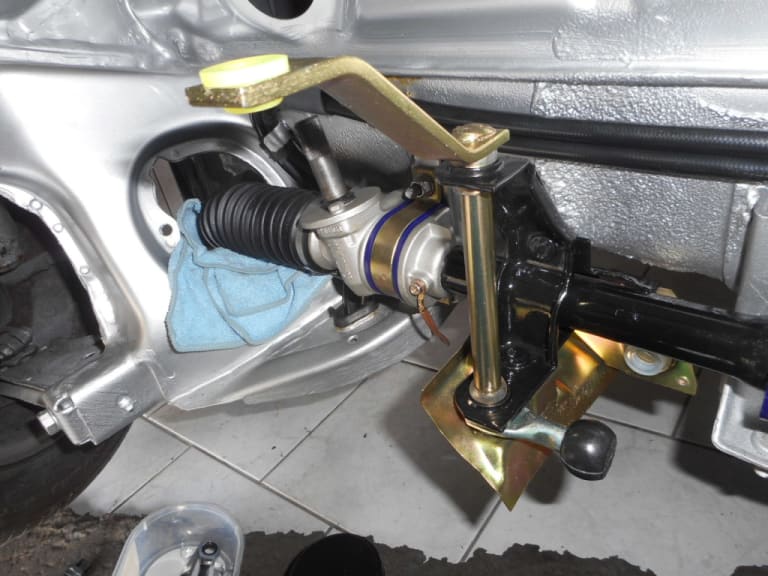
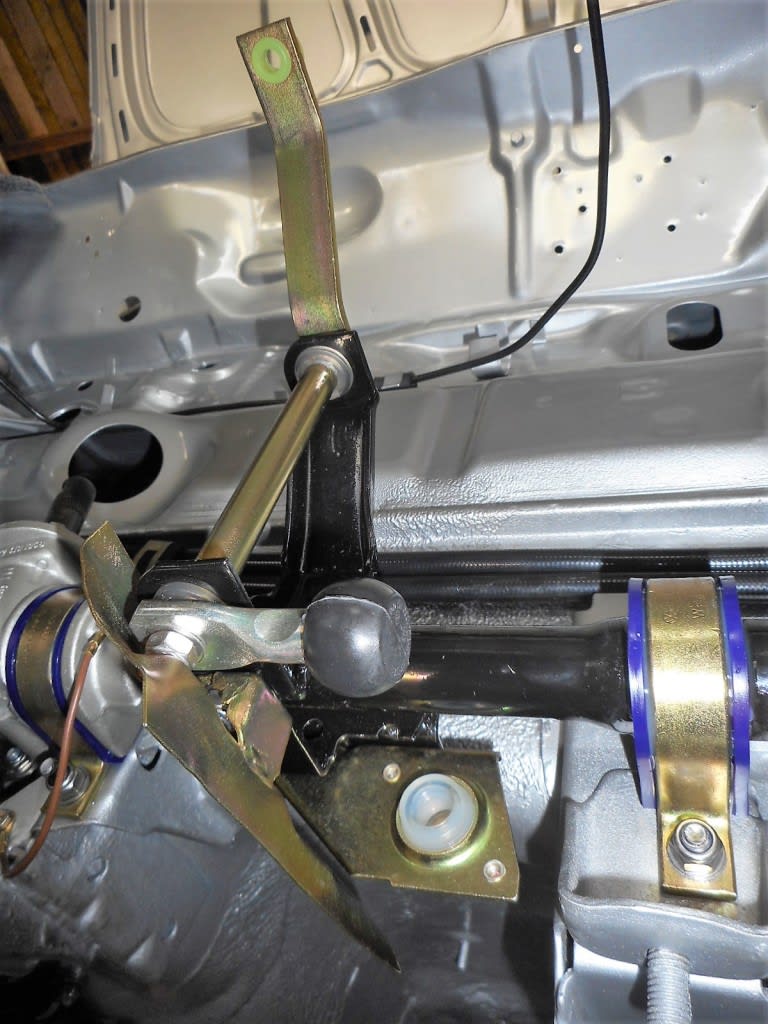
First was to finish off the steering rack.
The gear change linkage parts that fit to the rack - all plated/renewed.
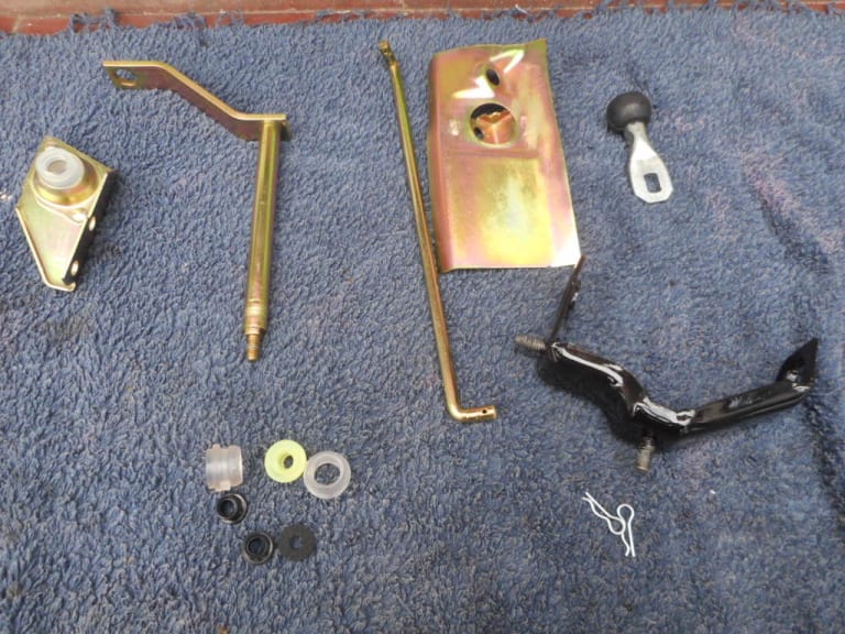
Lovely to be working with clean and new parts after all the messy jobs
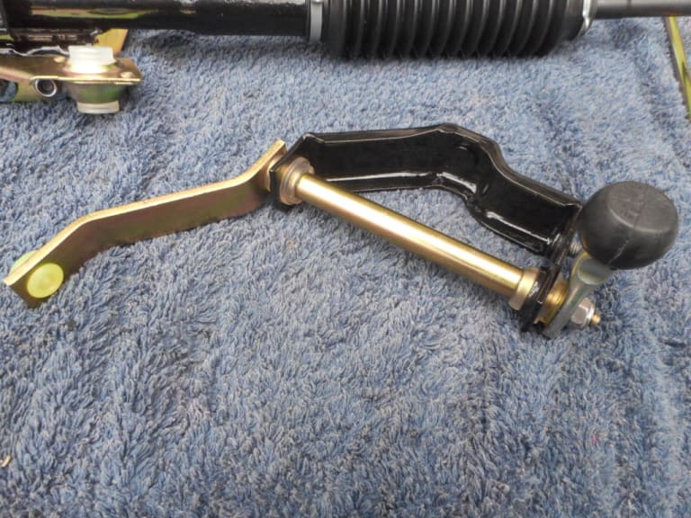
Rack fitted with new poly bushes. This should stiffen up the rack mounting to help less movement in the gear-change. I found that I couldn't fit it into the car with the gear linkage items attached - with the tie rods fitted there is "just" enough room to get the rack in.
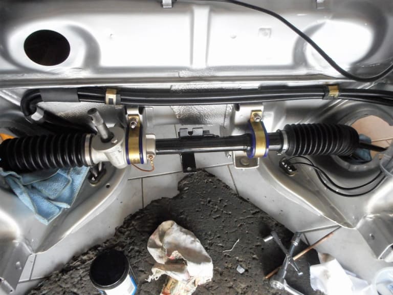
Made and new earth wire
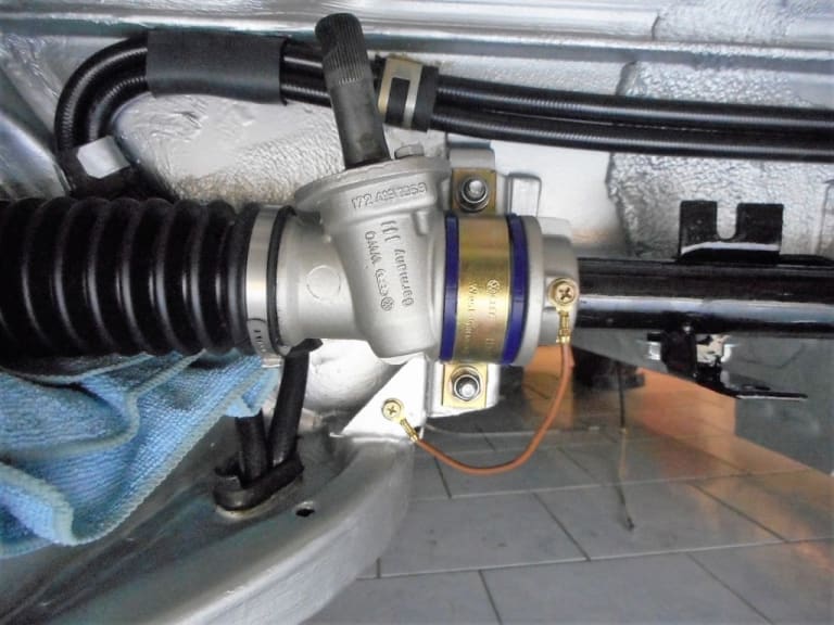
Gear-change parts and heat shield fitted
1983 Golf GTi Campaign Edition, Diamond Silver
http://vwgolfmk1.org.uk/forum/index.php?page=topicview&id=projects%2Fyour-mk1-golfs_2%2F-tag-1983-campaign&redirected=1#post_1551531
http://vwgolfmk1.org.uk/forum/index.php?page=topicview&id=projects%2Fyour-mk1-golfs_2%2F-tag-1983-campaign&redirected=1#post_1551531
Posted
Old Timer


I had bought a 9" servo some time ago and had already cleaned it up all ready. Now was the time to tackle clevis joint change required to mate it up to the MK1 brake linkage.
First off here are the differences between the MK1 and MK2 clevis joint.
MK2 servo on the left, MK1 on the right. The diameter difference is clear to see.
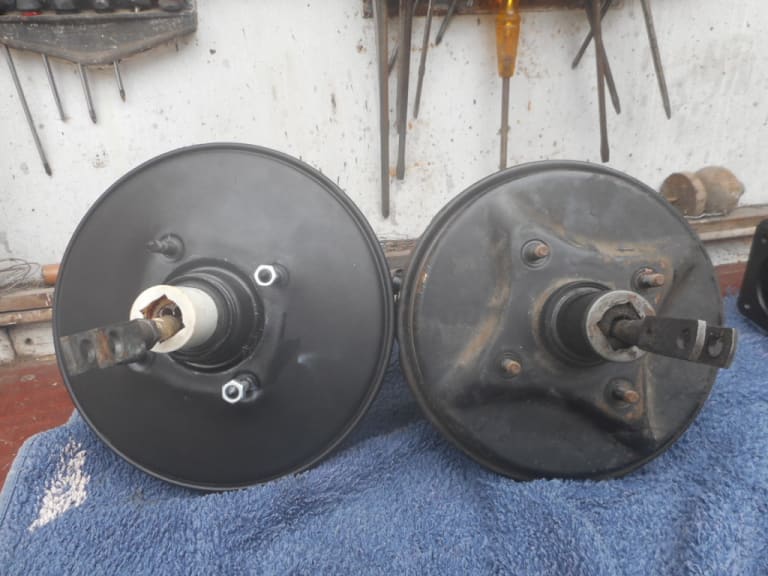
MK1 clevis has a rounded end and no lock nut behind it. Sorry for poor piccy - time to sack the photographer!
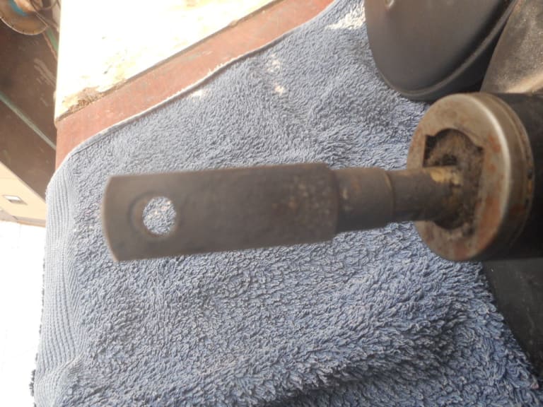
MK2 clevis has a square end and lock nut behind it
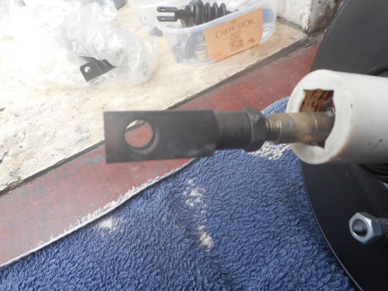
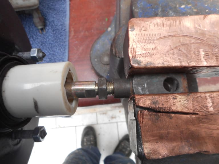
First loosen the lock nut on the MK2 and unwind the clevis joint from the shaft
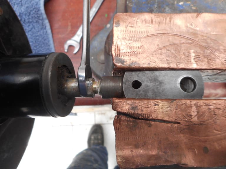
Unwind and remove clevis joint from MK1 shaft
Here are the two clevis joints. Mk1 above Mk2 You can now see that by placing the holes in line, the MK2 is shorter than the MK1 - measuring frm the hols back to the end of the clevis on the right.
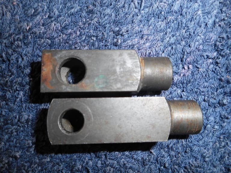
If you put the MK1 clevis pin into the MK2 hole - it rattles around. Clearly the MK2 takes a larger pin.
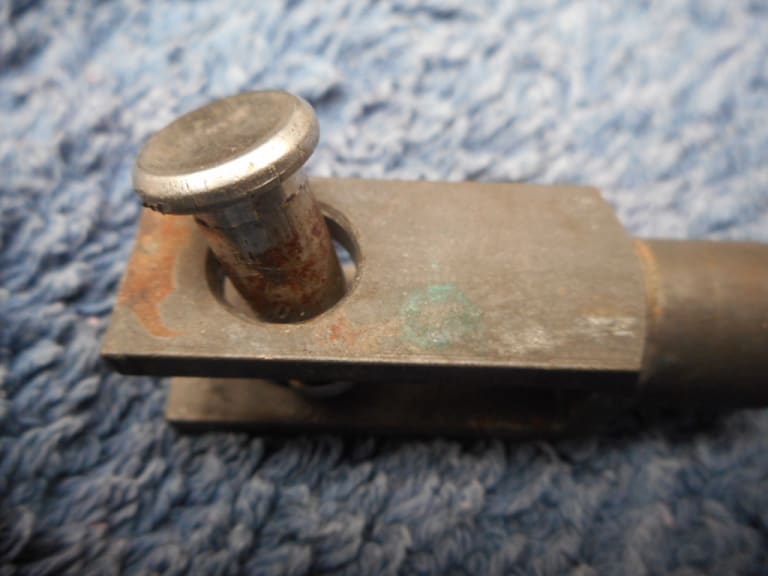
MK1 pin in MK1 clevis joint - a snug fit. So it is clear that if the MK1 clevis joint was fitted to the MK2 servo - the joint would not fir the MK1 brake linkage because of the different pin diameter.
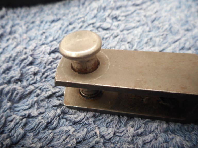
Second issue, as can been seen here after screwing the MK1 clevis onto the MK2 servo shaft, is that the servo shaft on the MK2 is too long for the MK1 clevis. This wouldn't matter except the servo linkage return spring has to hook through the smaller hole in the clevis joint, being obstructed by the longer shaft. Smaller hole hard to see in the pic - just above the thread to the right of the clevis pin hole. Again words will be said to the photographer - just not good enough!
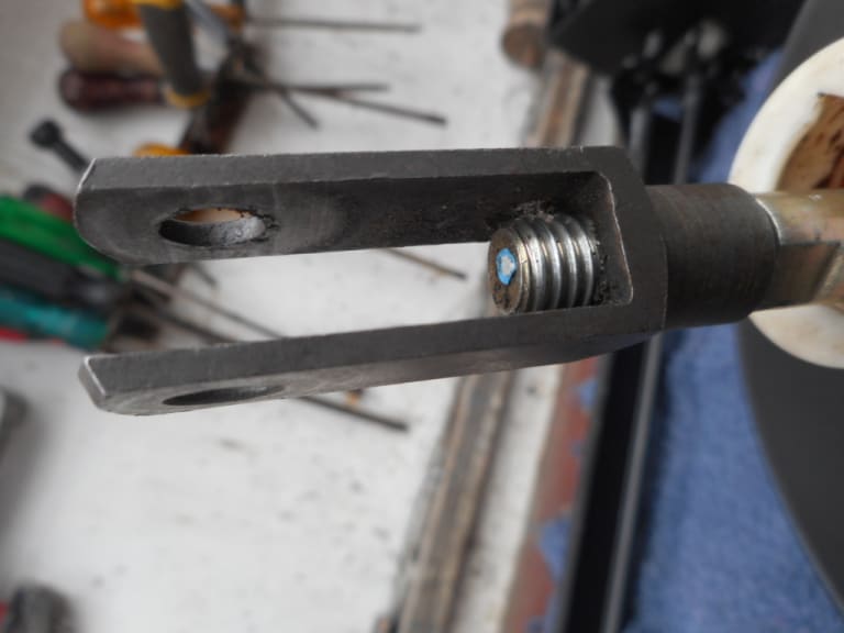
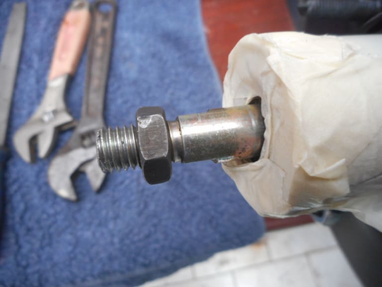
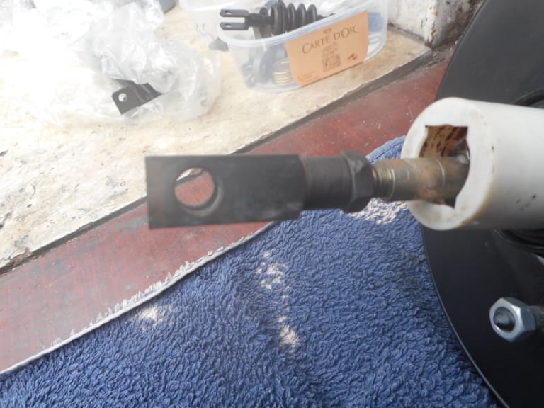
I screwed the MK2 lock nut back onto the MK2 shaft before hack sawing off the excess shaft - after careful measurement. Just under 10mm needed to be cut off. I could then undo the lock nut to make sure the end of the thread was not damaged.
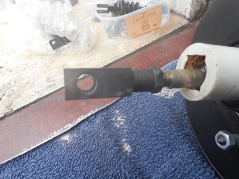
1983 Golf GTi Campaign Edition, Diamond Silver
http://vwgolfmk1.org.uk/forum/index.php?page=topicview&id=projects%2Fyour-mk1-golfs_2%2F-tag-1983-campaign&redirected=1#post_1551531
http://vwgolfmk1.org.uk/forum/index.php?page=topicview&id=projects%2Fyour-mk1-golfs_2%2F-tag-1983-campaign&redirected=1#post_1551531
Posted
Old Timer


Thankfully it was still present on the original servo - so carefully with small pliers I removed first the "horsehair" like outer layer and then the remains of the orange foam inner layer.
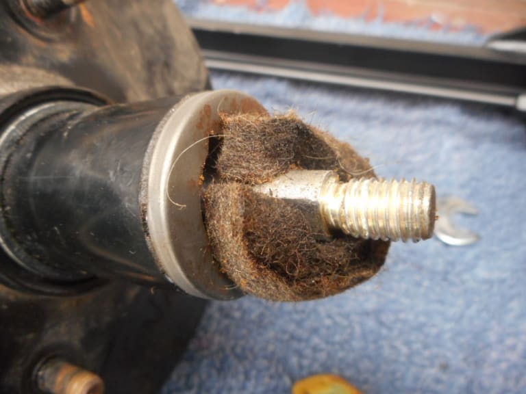
Using a bit old sponge I cut a new inner piece.
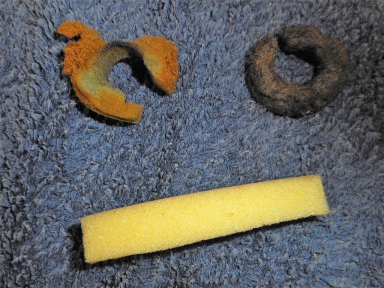
Before "stuffing" them back in
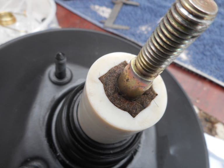
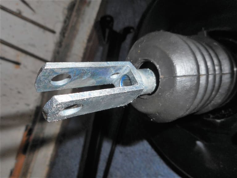
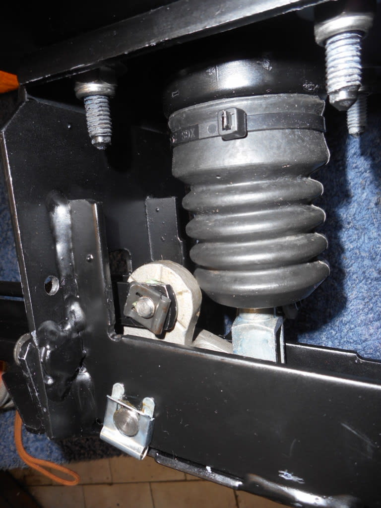
Slipped the boot on and wound on the MK1 clevis. Job done!
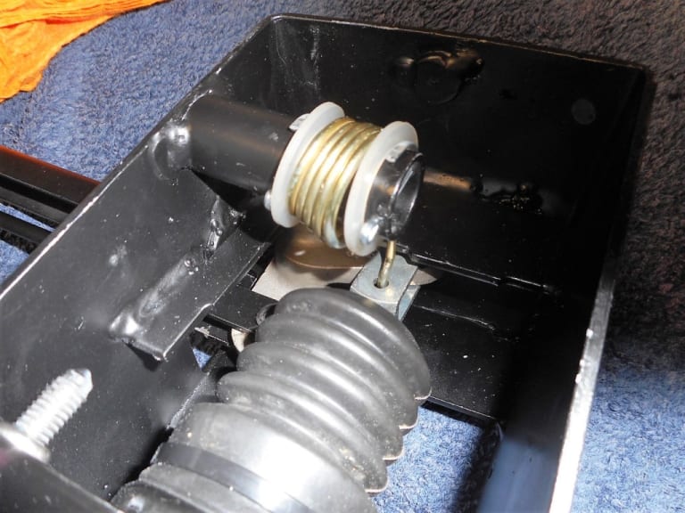
With the servo and linkage bar on a bench it wasn't hard to reattach the servo return spring and tricky final clevis pin to the linkage. Glad to be able to it on a bench and not in situ!
1983 Golf GTi Campaign Edition, Diamond Silver
http://vwgolfmk1.org.uk/forum/index.php?page=topicview&id=projects%2Fyour-mk1-golfs_2%2F-tag-1983-campaign&redirected=1#post_1551531
http://vwgolfmk1.org.uk/forum/index.php?page=topicview&id=projects%2Fyour-mk1-golfs_2%2F-tag-1983-campaign&redirected=1#post_1551531
0 guests and 0 members have just viewed this: None.


