FUEL GAUGE ISSUE HELP!!!!!!!
Posted
#1580240
(In Topic #213461)
Settling In

sorry if there is a topic which is the same however i couldn't see one
Okay Fuel gauge goes straight past full when ignition is switched on i read a lot of forums which pointed at the voltage stabilizer , i replaced this and it did not fix the issue, i wanted to go out in her today so i took the rear bench out and took out the lift pump/sender, i thought i would switch on the ignition and test the wiring with a voltage meter, however i noticed the fuel gauge didn't move i took out the internal plug for the lift pump and the fuel gauge worked went up and down accordingly however when i placed it in the tank to see how much fuel it would read it just shot straight back up, and of course when i reconnected the lift pump internal connector the fuel gauge shot straight past full, i'm sure this is an earth issue but i don't know where to look.
The car is MK1 Golf Cabrio 2.0 ABF Converted (Not by me)
Wires going to the plug
Brown 12v im sure this is supposed to be an earth
Red yellow 0v i'm guessing this is supposed to be the pump feed
Purple Black 0V fuel gauge wire
Any help would be greatly appreciated
Posted
Old Timer


I'm not sure of the wire colours for the pump and sender but brown is definitely earth, I'm surprised you have 12v on that. I would expect 12v on the one the feeds the pump when engine is cranking/running and maybe when you first power the ignition when the pump primes.
I'm pretty sure the gauge has 12v to it when the ignition is on and the negative of the guage connects to the sender and goes through a resistor to earth so you should probably have 12v to earth on that wire when the ignition is on.
If you use a continuity tester between the brown wire and the car body do you get a short circuit?
Mars red 1.8 GTI tintop now MOT'd and on the road!
http://vwgolfmk1.org.uk/forum/index.php?page=topicview&id=projects%2Fyour-mk1-golfs_2%2Fwent-to-look-at-a-golf&kfs79=150
http://vwgolfmk1.org.uk/forum/index.php?page=topicview&id=projects%2Fyour-mk1-golfs_2%2Fwent-to-look-at-a-golf&kfs79=150
Posted
Settling In

i put my voltage meter into the end of the connector that goes to the lift pump/sender,
Ya the brown has a constant 12v feed once the ignition is on so i will trace that and see were it goes and will report back.
Posted
Settling In

Yellow red wire is tapped into the live for the inline pump, brown is also tapped into to earth both fuel pumps and is correctly placed on the cluster of earths above the fuse box yet it has 12v i am guessing it has a break somewhere
Posted
Settling In

Posted
Old Timer


Also, do you have a continuity function on your tester and if so can you connect one lead to the brown wire where it connects to the pump/sender and the other to a good clean part of the body and see what reading you get.
If possible can you run a temporary wire from the brown on the pump/sender and connect it to the battery negative and see if that cures your problem.
I would say that 10v from the guage is probably about right.
Do the pumps run and does the car start/run ok?
Mars red 1.8 GTI tintop now MOT'd and on the road!
http://vwgolfmk1.org.uk/forum/index.php?page=topicview&id=projects%2Fyour-mk1-golfs_2%2Fwent-to-look-at-a-golf&kfs79=150
http://vwgolfmk1.org.uk/forum/index.php?page=topicview&id=projects%2Fyour-mk1-golfs_2%2Fwent-to-look-at-a-golf&kfs79=150
Posted
Settling In

i have tried running an earth direct from the sender cluster and cut the wire to the lift pump so it would just be the sender unit live and earthed and still no good, i tested the earth which splits into the main and lift pump and 0v so i think i was picking up the reading from the purple and back before just doent make sense it works when out of the tank.
Posted
Old Timer


Mars red 1.8 GTI tintop now MOT'd and on the road!
http://vwgolfmk1.org.uk/forum/index.php?page=topicview&id=projects%2Fyour-mk1-golfs_2%2Fwent-to-look-at-a-golf&kfs79=150
http://vwgolfmk1.org.uk/forum/index.php?page=topicview&id=projects%2Fyour-mk1-golfs_2%2Fwent-to-look-at-a-golf&kfs79=150
Posted
Local Hero

It takes the Ground from the tank, and through the potentiometer/rheostat sends that signal back to the gauge.
I don't recall it having 10V on it at all at the tank, but then again I have never measured for it 10V that is.
Electrically I suppose it is possible, I don't every remember looking for 10 at the sender sense.
The leg of the gauge (brass stud) should be tied to 10V on one side and the sense on the other.
Gauges do go flaky with cold solder joints, and age.
You might want to test the gauge with a 9V DC battery.
With that attached you should see 3/4 to full deflection.
From your original post, the Violet/brown is a return to the gauge
Brown is earth period. If you have 10V on it, then that is why you have 10V on the violet/black
REd wires are usually always 12V or b+ in.
Sounds as if your wires are crossed, and it could be at the take off point of the main pump, as the lift pump and main pump are tied at one point.
What do Divorces, Great Coffee, and Car Electrics all have in common?
They all start with GOOD Grounds.
Where are my DIY Links?
They all start with GOOD Grounds.
Where are my DIY Links?
Posted
Settling In

Regarding the gauge in the clocks i have fully tested all of these, when i checked the voltage stabilizer,
so can i just double check purple and black wire goes to sender, when the float moves the resistance either goes weaker or stronger and earths the remaining current?
Posted
Old Timer


Hope this helps and I hope you get it sorted.
Mars red 1.8 GTI tintop now MOT'd and on the road!
http://vwgolfmk1.org.uk/forum/index.php?page=topicview&id=projects%2Fyour-mk1-golfs_2%2Fwent-to-look-at-a-golf&kfs79=150
http://vwgolfmk1.org.uk/forum/index.php?page=topicview&id=projects%2Fyour-mk1-golfs_2%2Fwent-to-look-at-a-golf&kfs79=150
Posted
Settling In

Any tips on fitting scrapper seals cause i just cant seem to be able to fit them, i got the ones of vwheritage that are mk2 but state they fit mk1
Also windows are not working i have tested motors and they are working, comfort modular is clicking when i press the window button, just no motion.
any help will be greatly appreciated.
Posted
Local Hero

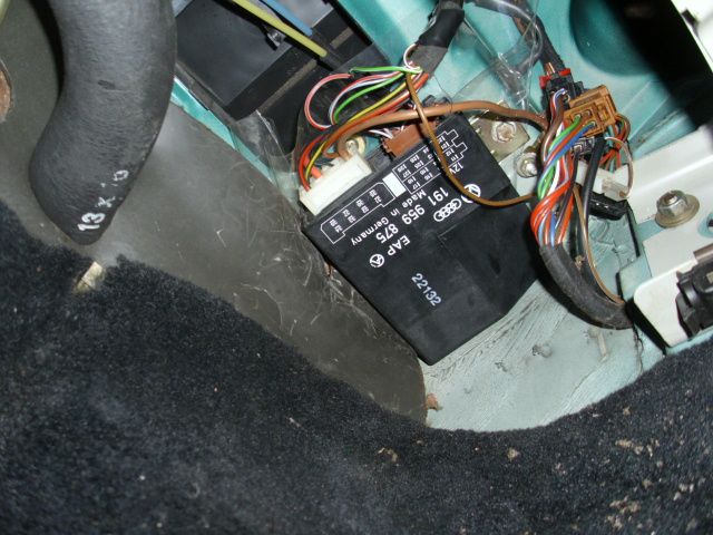
If you jumper 12V and Ground to the connectors on the module (brown ones ) and the windows go up and down, then it isn't your motors or wiring.
So that leads to one conclusion. Your Window Control module is bad.
They can go bad because of a few things. There isn't many components in them.


You can remove it, and take the case off using a couple of small flat blades.


Once out of the case you can inspect the relays for corrosion, and cold solder joints as well as rust water tracks. Has been known to fix a few bad controllers.
The usual culprit is that you have water migration from plugged rain drains that allows water to flow in to the fresh air inlet (on a/c equipped) and non-a/c equipped cars.
http://s3.photobucket.com/user/briano1234/media/TOPSeal/pont2rain.jpg.html
To remedy this remove or re-route the Vacuum line that goes up the middle, Re-route the Windscreen washer line that comes in the side and up the middle, you want that sucker clean.
Re-route of washer and vacuum lines in my Cabriolet to keep that sucker devoid of crud.
http://s3.photobucket.com/user/briano1234/media/heater%20vent/heater007-1.jpg.html
You need to make a Debris Guard for your hood vents.
http://www.toplessrabbit.com/forums/viewtopic.php?f=27&t=1509&p=27750#p27750
Ok, lastly if you don't have a rain divertor, then get one. It allows water from the hood vents to be routed to the drain areas….
non-a/c
https://mk1engineering.myshopify.com/products/vw-mk1-golf-rabbit-jetta-rain-tray-scuttle-cover
Here is a home made window controller.
http://forums.vwvortex.com/showthread.php?5059297-Home-made-power-window-controller-for-90-something-cabby
Everythign I know about this part is:
4 pages long, read it all.
A1 Cabbie Power Window Problems | VW Vortex - Volkswagen Forum
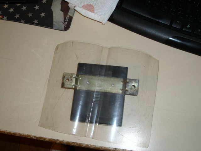
Lastly, create a water divertor from a CD Case or Plastic and screw over the assembly to divert water off the wires and controller box.

Look closely and you will see I have it puckerd on the left to divert any and all water off the controller and on to the floor.

What do Divorces, Great Coffee, and Car Electrics all have in common?
They all start with GOOD Grounds.
Where are my DIY Links?
They all start with GOOD Grounds.
Where are my DIY Links?
0 guests and 0 members have just viewed this: None.


