


Fader / Balance Switch Wiring

Posted
#1538182
(In Topic #205449)

Settled In

Trying to connect four speakers to Blaupunkt Hamburg
Picked up the below switch, in order to connect four speakers to my Blaupunkt:
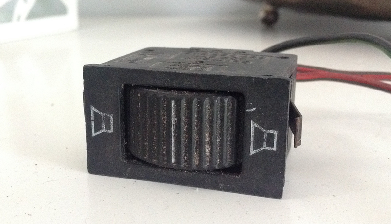

but it how do I connect 4 speakers to the switch, all the speakers I have had in the past have 2 wires running to them but this switch only seems to allow for 1 wire per speaker??
On the back of the switch is:
(Please correct me if I'm wrong!)
L - Left input?
R - Right input?
VR - Front Right?
VL - Front Left?
HR - Back Rear?
thanks in advance
Adam
�
Posted
Old Timer

L + R which is self explanatory
HL - rear / left
HR - rear / right
VL - front / left
VR - front / right
I'm assuming your radio has 2 x built in speaker feeds on its rear (L+R), which is the set-up for which this fader was intended.
I'm also assuming that you are using the old . (dot) and - (dash) style speaker wire connectors.
All of the six pegs on your switch must be utilised to make it work correctly.
The top three (HR / R / VR) will combine to become one sub loom and (HL / L / VL) a second.
Each 3 wire sub loom is spliced part way along its length to create between them, an additional 6 wires at the radio end
In combination these 12 wires will ultimately create 6 speaker connectors… 2 of which are male and 4 of which are female, (divided evenly between each sub loom - ie. 1 male and 2 x female).
�
Posted
Settled In
Thanks for the response, your assumptions are spot on, unfortunately I think I am really being daft but do you mean it should be wired as below? (Apologies for the terrible drawing, have only done one side too!)
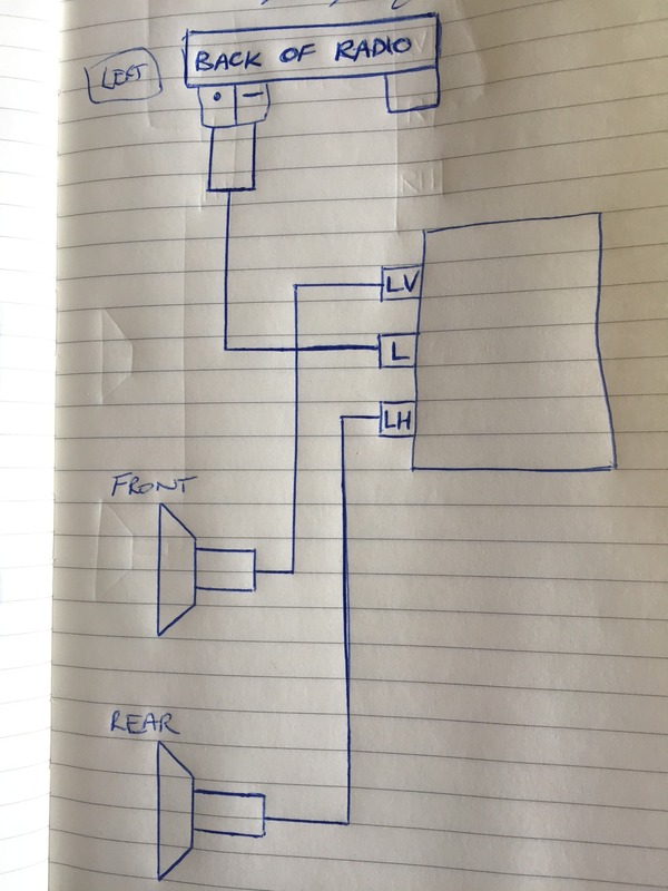
Is that anywhere close? I'm pretty sure it's wrong but it's all my sleep deprived head can make of your thorough instructions!
Thanks again
Adam
 Last edit: by Ad2408
Posted
Old Timer
Each of your four speakers will have 2 x wires leading from them… One is a positive and the other a negative.
To keep this straightforward, I will assume you are using the old dot / dash type connectors throughout.
The dot is the positive and the dash the negative.
Connect a male dot/dash connector to the radio end of each individual pair of speaker wires
Set these to one side for the moment.
Your switch… You will need to make a loom with 4 x female connectors to plug the speaker wires into and 2 x male connectors that go into the L+R terminals on the sets rear (where the existing speakers would currently be connected)
If you were to wire straight to the switch from the speakers you'd find fitting and removing the radio would involve taking part of the dash out every time as the switch snaps into its aperture from the front, not behind.
The switch only uses positive wiring to the 6 x pegs on the rear.
This explains why only a single wire goes to each of its pegs.
These run from the switch (via the looms connectors) to the 4 x individual positives from the speakers, plus each of the positives for the L+R� speaker terminals on the sets rear.
At this point each of the looms male and female connectors will have an as yet unused neg. wire coming from it… four will connect to the negative side of each speaker and two for the negative side of the L+R speaker terminals on the sets rear.
Make sure these are correctly split into their left and right sides (three to each), as in the 2nd diagram below.
Treat each as a separate bundle, connecting only to the others in the same bundle.
For want of a better description, your loom should now have in addition to the 6 x live wires running to the switch, 2 x dead end bundles (each of 3 neg. wires). Insulate the bundles ends, they aren't connected to anything other than themselves.
You will now have a loom attached to your switch with 4 x female connectors and 2 x male connects at its end.
The looms 2 x male connectors go into the L+R terminals on the sets rear.
The wires from each of your 4 x speakers go to their corresponding female connections on the loom.


You are aiming for this…

�
Posted
Settled In
Thanks again for the really comprehensive answer!
I think I now understand…
Is the below correct?

�
Posted
Old Timer
In the method I explained the male connectors from the switch, (that go into the rear of the set) will have the negative feed for the speakers incorporated into them when you create the two bundles I described
This 2nd way will have the negative side coming in separately and straight from the speakers (which still have to been spliced together somewhere along their length anyway).
�
Posted
Settled In
Thanks so much for the help, struggling to get my head round what you mean tbh, but if it will work I will be happy.
The pos/neg for the speakers (already in position) run together so I won't split them and so will probably need to alter the way I do it inline with how the wires run.
Thanks again
Adam
Posted

Life Member


Just adding this for reference as the old pictures have been deleted.�

0 guests and 0 members have just viewed this: None.