Dash clock clip wiring
Posted
#1598784
(In Topic #217436)
Settled In

What wires do what
Its not the best description so if more information needed then just ask lol.
Cheers in advance.
Posted
Local Hero

What do Divorces, Great Coffee, and Car Electrics all have in common?
They all start with GOOD Grounds.
Where are my DIY Links?
They all start with GOOD Grounds.
Where are my DIY Links?
Posted
Settled In

Posted
Local Hero

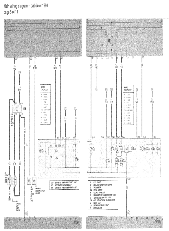
The Pins of the connector are on the top of the Cluster Highlight.. labeled as t14/2 (brown) ground, and t14/14 Black B+(12v) input

Yeah I know a Charappy snap it is but an example that you will find in the Bentley/Haynes
What do Divorces, Great Coffee, and Car Electrics all have in common?
They all start with GOOD Grounds.
Where are my DIY Links?
They all start with GOOD Grounds.
Where are my DIY Links?
Posted
Settled In

Posted
Local Hero

But the feed actually came off the Fuel pump relay on the 90's and earlier.
What do Divorces, Great Coffee, and Car Electrics all have in common?
They all start with GOOD Grounds.
Where are my DIY Links?
They all start with GOOD Grounds.
Where are my DIY Links?
Posted
Settled In

Posted
Local Hero

The rev counter input is red/black pin 5.
I have a how to increase the tension on the pins by carefully removing the shroud and the mylar off the tongue, then using one piece of Electrical tap on the pad side of the tongue then replace the mylar, and the shroud.
The rev counter (also called a Tachometer/ Tach for short) is powered on the 90's by the fuel pump relay vial the coil input.
The fuel pump relay only fires when the shutter on the hall sender is covered (as when a plug gets spark). This is happening on a running engine it appears that the Fuel pump relay is on all the time, as your DVOM can't react fast enough to show you this. It is these pulses from the coil that produce the Tachs count of the Revolutions of the engine. At the tach signal input to the cluster red/black you will see basically 12V there.
but in actuality it is 12V Pulsed.
Check to see if you are getting 12v at the red/black wire on a running engine, if not (that is in relation to frame as well as pin2 (brown)) if not then verify that pin2 is 0 ohms to ground,,,
In the archive section of the forum under how-tos I have a plethora of DIY's for the Cabriolet (90's )
While the DIY engine is for Digifant, most all others apply to the MK1's in general.
Oh there is a link to them in my signature "where are my diy's".
What do Divorces, Great Coffee, and Car Electrics all have in common?
They all start with GOOD Grounds.
Where are my DIY Links?
They all start with GOOD Grounds.
Where are my DIY Links?
Posted
Settled In

I've managed to get the rev counter working. I noticed a black wire not attached to anything coming from the white clip that connects to the back of the clock's (dials).
So I started looking further down the loom for a matching wire and BOOM!!! found one connected it and sorted. Buzzing all working now. Plus for my freshly built engine and car I've also reset the miles on my clock's to match and gave them a full clean and some nice bright led's.
Thanks for your help guys 😁.
Posted
Local Hero

What do Divorces, Great Coffee, and Car Electrics all have in common?
They all start with GOOD Grounds.
Where are my DIY Links?
They all start with GOOD Grounds.
Where are my DIY Links?
0 guests and 0 members have just viewed this: None.


