Skip navigation

Vacuum Hoses - help please

Post

Back to the top

Vacuum Hoses - help please

Hi all, have a 1.8gti k-jet engine built from parts that I am tring to use and there are hoses missing which are part of the vacuum circuit from inlet manifold to air box etc. The Inlet manifold I have is one with the throttle body on the side of the cam belt (on the left) can anyone provide me with a circuit layout or possibly description or pics for vacuum hoses for engines with this type of IM. Most of the ones I can find seem to be the other way round. Really appreciate any help.

Post

Back to the top
all mk1 gti's had throttle on gearbox side of block. if you want to put it on the otherside (cambelt) ???????? then you'll be better off looking at a mk2 gti layout.

Post

Back to the top
Think your best using a mk1 inlet manifold and that inducts from n/s, otherwise your going to have to fit brackets etc for airbox and relocate washer bottle from O/S for no obvious benefit.

Cheers

1981 1600 GTI (coming to a road near you soon…)

1983 1100 C

Post

Back to the top
see if this helps..


Post

Back to the top
I have a different vacuum line configuration (on a 1.8DX FI Cabrio GTI 1985) which I know is incorrect, and wonder if it makes the car's performance suffer.

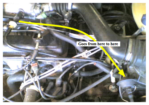
The vacuum line to the distributor does not come from the nipple on the back of the throttle housing, which appears to have been blocked with something.

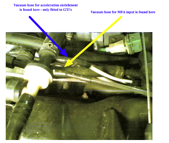
It comes from one of the  nipples on the brake servo non-return value (the one which should feed the cold acceleration vacuum sensor, the other one is broken off with a screw stuffed in it UGH!)
 
Does anyone know whether not coming directly from the throttle housing would affect the sensitivity of the vacuum advance and therefore acceleration power.

Power develops rather slowly, although this could be just ignition timimg (set for 95 octane) or general old age (150k miles)

Post

Back to the top
the vacuum to the distributor is required for advance /retard adjustment  - the Germans didn't put this together for interest - they did it for very good reasons.  i would suggest reverting to manufacturers spec

MP

Post

Back to the top
The set up on my car seem to be a bit different… I have the vacuum going to the distrbutor and the vaccum for the mfa, the other one next to the mfa was snapped off when I bought the car, and when the engine was running it was sucking in air. I taped that up. It is just a little slow on tick over now. Ive looked at other cars at shows and the one next to the mfa has a blank end. Are there different set ups? I'm confuesd!!!

83 Mars red GTI

01 V6 4Motion (daily driver)

09 Golf GTI MK6, candy white, superchipped!

Post

Back to the top
No problem with going back to the correct configuration. Manufacturer's spec is always the best option. However I have to get the dammed plug out of the throttle housing. It may require drilling.

I was just interested to know whether a distributor advance/retard vacuum feed from the front of the inlet manifold ( i.e. the cold enrichment nipple on the non return valve) would make any difference from one taken the throttle housing. More or less sensitive to manifold pressure change for example.

If it made no difference, then I might not bother.

Post

Back to the top
thats a really good question.
i think it could have an effect, tho i dont know why really, just strength of vacuum could be different. i think mines set up wrongly having looked at those pics, ill try it 2moro

rebuild in progress....

Post

Back to the top
bump so i can find this easier

rebuild in progress....

Post

Back to the top
would dubdaves run differently due to the location of the dizzy advance vaccum ie not on the tb?

yep
i reckon!

rebuild in progress....

Post

Back to the top
My clipper, is not idling or revving correctly! I have changed everything I can think of and now I am left with the vacuum hoses!! Can anyone suggest why between idle and 2500 rpm the car would be struggling?? It's fine when running cold but is very difficult to pull away once warmed up without stalling!!! Any help would be appreciated!!!

Post

Back to the top
Those photos are a little confusing.

 DX1.8gti
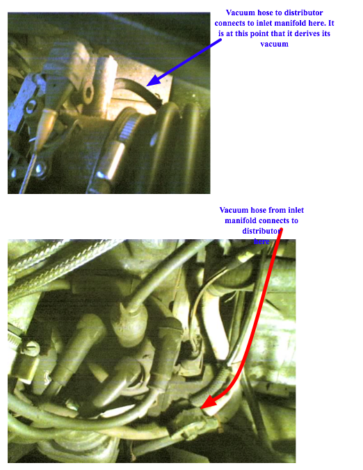
Vac pipe from throttle body goes to the distrib for retarding/advancing.
 
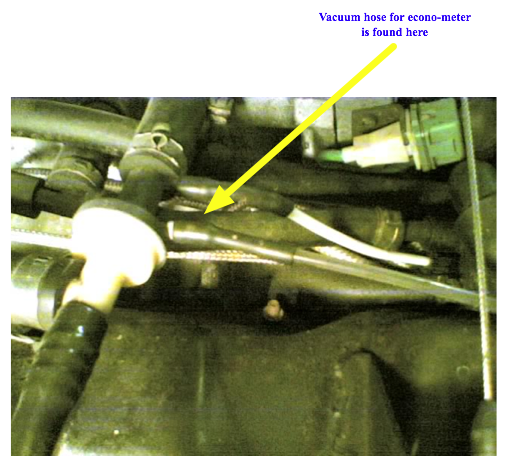
Vac pipe from 1 of the connections on top (by rocker cover) goes to the MFA.

if there is 2 connections (usually is) block it off.

this is how my setup is, and to be knowledge correct.

<a><img></a>
0 guests and 0 members have just viewed this: None.