


Early fuse box wiring help fuel pump starter loose wires

Posted
#1123237
(In Topic #134326)
Settling In

Early fuse box wiring help fuel pump starter loose wires
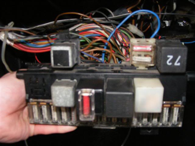
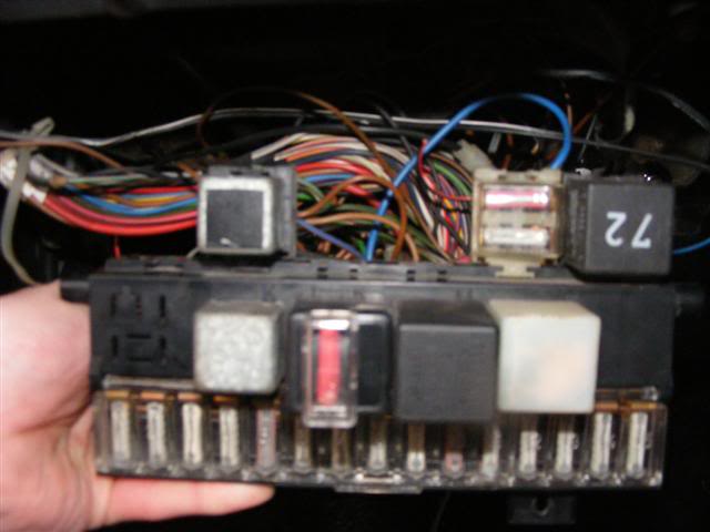
The car is a vw golf mk1 gti 1.8 8v it has the early type fusebox its an x-reg
The loom was taken out while some work was done and upon replacing it a few wires and there locations are a mystery!
Also an old alarm was removed, i believe the alarm tapped into the fuel pump wiring,
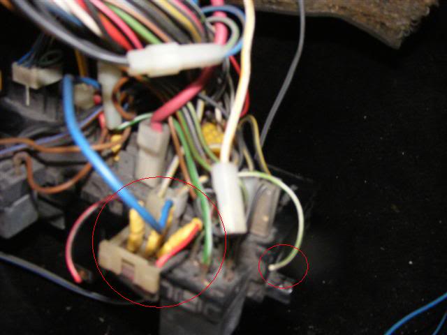
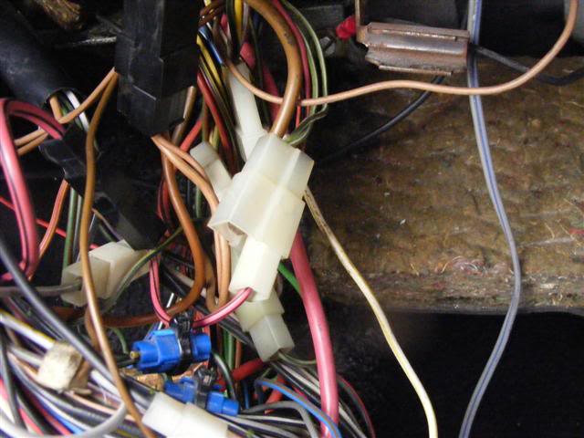
Ok i have a red and yellow wire fropm the main fuel pump, not sure where that goes on the back of the fusebox
Secondly there is a red and also a red and white wire from the enginebay loom has a spade terminal on, not sure where that goes,
There is a white and yellow wire with an insulated spade terminal, note sure where that goes,
There is a grey and green thin wire that is also not attached. see picture.
And there is a fuse holder slotted onto the top of the fusebox that has a blue wire jumped across from the back of the fusebox going into it but the two wires coming out of it are cut and go to nothing, my guesses are that this is somthing to do with the old alarm/fuel pump
and that maybe the red and yellow wire and or the red and the red and white wire may go to this??
Ive attached some pictures and circled the said wires
I hope someone can help or shed some light my brain hurts

Posted

MOTY 2013

http://www.vwgolfmk1.org.uk/modules.php?name=Forums&file=viewtopic&t=101628
the other wires which are left over you need to trace them back to where they go, and work out the functions using the fusebox sticky at the top of this section, plus this wiring diagram should help you (read the how to read vw wiring diagrams link in howto section if you get stuck)
Google Sites: Sign-in
Hello my name is John and I'm a dub addict.
My wiring diagrams and other documents have moved here:
VAG Documents & Downloads
You'll need to sign into google/gmail for the link to work! (its free!)
My wiring diagrams and other documents have moved here:
VAG Documents & Downloads
You'll need to sign into google/gmail for the link to work! (its free!)
Posted
Settling In
what would be really helpful is if someone with exactly the same fusebox can have a look at theres and advise me, as im also not so good with the wiring diagrams and im sure i tried to read one but it did not help me locate the positions for said wires.
Posted
MOTY 2013

have a read of this:
http://www.vwgolfmk1.org.uk/modules.php?name=Forums&file=viewtopic&t=38676
it takes you through how to read vw wiring diagrams. once you get your head round it you'll find it much easier to sort thru your wiring.
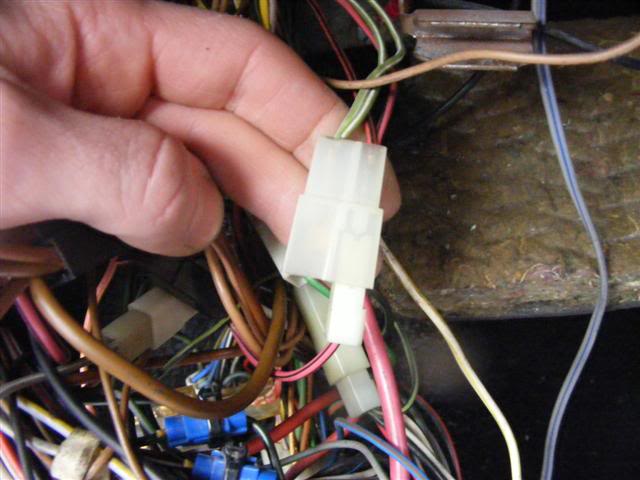
on the diagram I linked you to, the fuel pump is on page 2 marked 'G6' near the bottom. the fuel pump relay is at the top, marked 'J17'. with a bit of head scratching you can see the fuel pump power wire comes from plug A pin 8, then runs to the 3 way jumper block I mention above marked 'T'
the pump wire colour is marked sw/gn (black/green) on the diagram but I've also seen them in brown/black, and red/yellow
Hello my name is John and I'm a dub addict.
My wiring diagrams and other documents have moved here:
VAG Documents & Downloads
You'll need to sign into google/gmail for the link to work! (its free!)
My wiring diagrams and other documents have moved here:
VAG Documents & Downloads
You'll need to sign into google/gmail for the link to work! (its free!)
Posted
Settling In
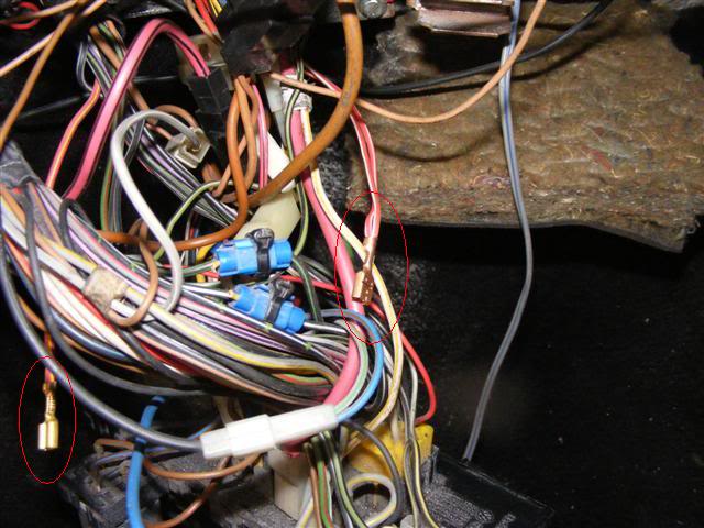
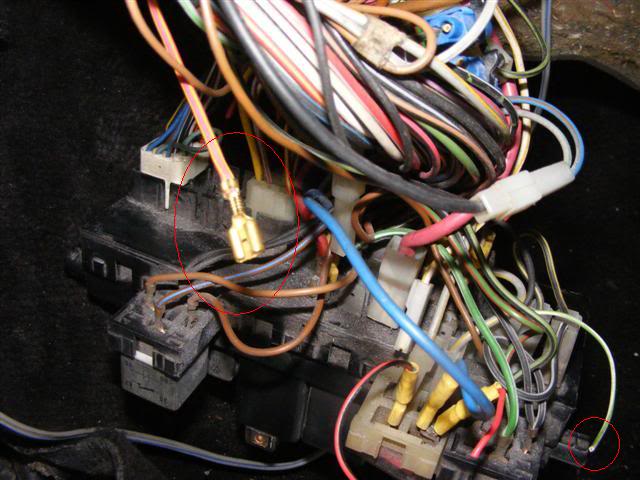
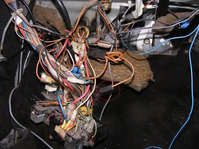
I just now need to sort the following-
see picture-
Brown earth wire with blade insulation on spade is this the main earth for the fusebox?
the white and yellow not sure where that goes,
the other wire circled and the two coming from the fuse on the top of the fusebox as circled in picture.
Posted
MOTY 2013
white/yellow is likely to be the front fogs, i wouldnt worry about them for now just make sure non of them are shorting out anywhere then check the electricals to see if everything is working. if so, great no need to worry. if not, that will help you narrow down what you need to look at both in the car and on the fusebox diagrams
Hello my name is John and I'm a dub addict.
My wiring diagrams and other documents have moved here:
VAG Documents & Downloads
You'll need to sign into google/gmail for the link to work! (its free!)
My wiring diagrams and other documents have moved here:
VAG Documents & Downloads
You'll need to sign into google/gmail for the link to work! (its free!)
Posted
Settling In
Can anyone out there just take a quick look at there fusebox and tell me if this is the case.
Posted

Old Timer

1982 Non Sunroof Black 1600 GTI
2003 MKIV Golf PD150 GT TDI
2003 MKIV Golf PD150 GT TDI
Posted
Settling In

Posted
MOTY 2013
Hello my name is John and I'm a dub addict.
My wiring diagrams and other documents have moved here:
VAG Documents & Downloads
You'll need to sign into google/gmail for the link to work! (its free!)
My wiring diagrams and other documents have moved here:
VAG Documents & Downloads
You'll need to sign into google/gmail for the link to work! (its free!)
Posted
Settling In
there is fuel but just no spark,
Im not sure if its somthing ive done with regards to wiring as basically it was a remove and refit.
Any ideas anyone?
Posted
MOTY 2013
Hello my name is John and I'm a dub addict.
My wiring diagrams and other documents have moved here:
VAG Documents & Downloads
You'll need to sign into google/gmail for the link to work! (its free!)
My wiring diagrams and other documents have moved here:
VAG Documents & Downloads
You'll need to sign into google/gmail for the link to work! (its free!)
Posted
Settling In
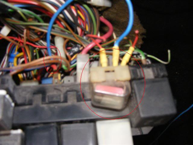
The thermo switch for the cold start and also the cold start valve have a green and white wire this goes into the loom and where it comes out behind the fusebox it is not plugged into anything see picture-
Any idea what plugs into this, i have tried and tried with the wiring diagrams but to no avail,
anyone with a mk1 gti with early fusebox just what to take a peek and tell me..
Also the coil when ignition is off both sides of the coil show 12v negative, when ignition is switched on both sides show 12v positive and when cranking it drops to about 7v
Posted
Settling In
Posted
MOTY 2013
Hello my name is John and I'm a dub addict.
My wiring diagrams and other documents have moved here:
VAG Documents & Downloads
You'll need to sign into google/gmail for the link to work! (its free!)
My wiring diagrams and other documents have moved here:
VAG Documents & Downloads
You'll need to sign into google/gmail for the link to work! (its free!)
Posted
Settling In
Posted
Settling In
Posted
MOTY 2013
4 TCI-H Switch unit - testing
1 When making this test, the coil must be in good condition.
2 Remove the plastic cover on the right-hand side of the plenum chamber for access to the switch unit (see illustrations).
3 Disconnect the multi-plug from the switch unit and connect a voltmeter between terminals 4 and 2 (see illustration).
4 Switch on the ignition and check that battery voltage, or slightly less, is available. If not, there is an open-circuit in the supply wires.
5 Switch off the ignition and reconnect the multi-plug to the switch unit.
6 Pull the multi-plug from the Hall sender on the side of the distributor (see illustration), then connect a voltmeter across the low tension terminals on the coil (see illustration).
7 Switch on the ignition and check that there is initially 2 volts, dropping to zero after 1 to 2 seconds. If this is not the case, renew the switch unit and coil.
8 Using a length of wire, earth the centre terminal of the distributor multi-plug briefly. The voltage should rise to at least 2 volts. If not, there is an open-circuit or the switch unit is faulty.
9 Switch off the ignition and connect the voltmeter across the outer terminals of the distributor multi-plug.
10 Switch on the ignition and check that 5 volts is registered on the voltmeter.
11 If a fault still exists, renew the switch unit.
12 Switch off the ignition, remove the voltmeter and reconnect the distributor multi-plug.
5 Hall sender - testing
1 Check that the ignition system wiring and plugs are fitted correctly.
2 The coil and TCI-H unit must both be in good condition.
3 Pull the HT lead from the centre of the distributor cap and earth it to the engine or bodywork.
4 Pull back the rubber boot from the switch unit and connect a voltmeter between terminals 6 and 3 (see illustration).
5 Switch on the ignition and turn the engine by hand in its normal direction of rotation. The voltage should alternate from between 0 and a minimum of 2 volts. If not, the sender is faulty and must be renewed.
Hello my name is John and I'm a dub addict.
My wiring diagrams and other documents have moved here:
VAG Documents & Downloads
You'll need to sign into google/gmail for the link to work! (its free!)
My wiring diagrams and other documents have moved here:
VAG Documents & Downloads
You'll need to sign into google/gmail for the link to work! (its free!)
0 guests and 0 members have just viewed this: None.