VW's Twincharger System
Posted
#1323078
(In Topic #159861)
Settling In

A brief overview of how VW's twincharger system works
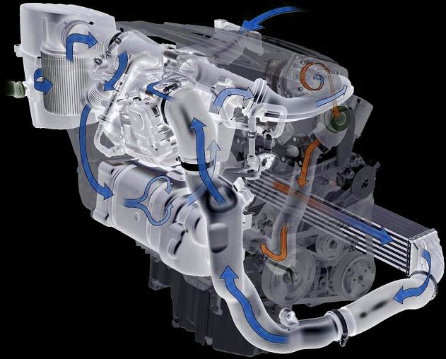
This engine is a combination of a roots type blower couple with exhaust gas driven turbocharger ensuring a quick throttle response and power at all engine speeds.The roots blower on this engine cuts in at approx. 1500rpm and in most situations cuts back out again at 2400rpms and is quite a large size for high efficiency.At the latest 3500rpm the turbocharger then takes over with sufficient exhaust gases being sent through the manifold. This set up enables a higher compression ratio of 10.0:1 for increased efficiency and better fuel consumption.THE TWINCHARGER SYSTEM:Fresh air is drawn in through the air filter. The position of the control flap determines whether or not the air is drawn in through the supercharger and/or directly to the turbocharger. The air from the turbocharger then flows through a charge air cooler and throttle valve control unit and into the inlet maniold.OPERATING RANGES:This diagramme shows the operational ranges of the roots type supercharger, turbocharger and cross over points incorporating the two. Depending on torque requirements, the ECU decides whether, and if so how the required charge pressure is to be produced.The turbo operates throughout the green range and note how the turbocharger alone cannot produce the desired charge at low engine speeds. The supercharger operates in the lower area (dark grey) and a combination thereof in-between.

DARK GREY: Continuous charging via roots blower activated from the minimum torque range (approx 1500rpm) to change over point at 2500rpm.Pressure is regulated from the control flap unit.LIGHT GREY: The supercharger is activated in response to demand up to a maximum speed of 3500rpm. This is needed, as an example; if the vehicle is driven at a constant speed and then a sudden burst of acceleration is added via throttle input. This also overcomes the lag associated via low inertia at low exhaust gas speeds with solely turbochargers.GREEN: The exhaust gas is now up to speed and flow so the supercharger is disengaged and the turbo takes over. Charge presure is regulated by charge pressure limitation solenoid valve N75.
IMPLEMENTATION OF OPERATING RANGES:The engine load and speed range allows the ECU to determine how the air flows into the cylinders for the desired torque. The ECU also decides whether or not the turbo alone can generate what is required or the supercharger is needed.
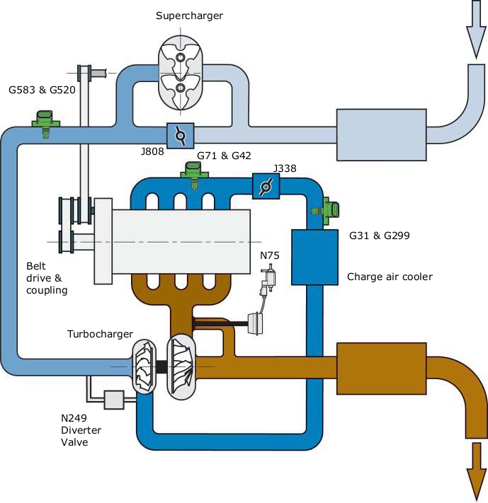
NATURALLY ASPIRATED OPERATION AT LOW ENGINE LOAD:In NA mode the control flap is fully open and flows directly to the turbo. Although the turbo is driven by exhaust gas the energy of the exhaust gas is so low that only a small charge pressure is produced. The throttle valve is opened in accordance with the drivers input and a vacuum is produced inside the inlet manifold.
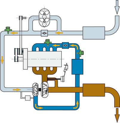
SUPERCHARGER AND TURBO OPERATION AT HIGH ENGINE LOAD AND SPEEDS UP TO 2400RPMDuring this period the control flap is closed or partially open to regulate the charge pressure. The supercharger is operated by a solenoid coupling and driven by the superchargers belt drive. The supercharger induces the air and compresses it before pumping it to the turbocharger. The air is then compressed further within the turbocharger. The charge pressure of the supercharger is measured by the inlet manifold pressure sender G583 and regulated by the control flap unit J808. The total charge pressure is measured by charge pressure sender G31. The throttle valve fully open an absolute charge pressure of 2.5bar is present in the inlet manifold.
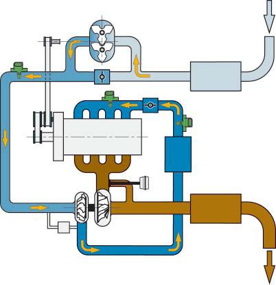
As it approches 3500rpm for the change-over

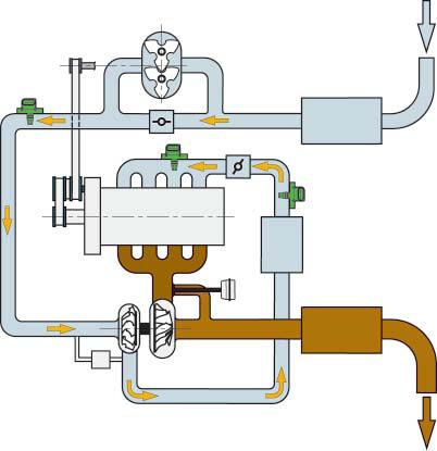
EXHAUST GAS TURBOCHARGER OPERATION:Above approximately 3500rpm the turbo alone can produce the required gas pressure at any point. The control flap is fully open and the air is induced directly to the turbocharger and the turbo can produce enough energy required for the charge pressure. The throttle valve is fully open and an absolute pressure of 2.0 bar can be found in the inlet manifold. Charge pressure sender G31 measures the charge pressure and is regulated via the N75 valve.
ROOTS TYPE SUPERCHARGERAdvantages: Quick charge pressure build up, high torque at low engine speeds, no external oil and lubrication necessary, activated on demand only.Disadvantages: Consumes engine power due to pulley system, charge pressure is generated depending on engine speed and then regulated, with the result that some of the energy is again then lost.EXHAUST GAS TURBOCHARGERAdvantages: Very high efficiency through the use of exhaust gas energy.Disadvantages: In a small engine like the 1.4 the charge pressure generated at low engine speeds may not be enough to produce a decent amount of torque. High thermal load.
DRIVE SYSTEM:The supercharger is activated when required and driven via the coolant pump via an auxiliary drive. This drive is activated by a maintenance free solenoid coupling on the coolant pump module. If the solenoid coupling is deactivated, three lead springs pull the friction plate back into it’s initial position and due to the high forces involved “clicking “is normal. Due to the ratios from thecrankshaft pulley to the roots supercharger pulley, as well as the internal ratio of the supercharger, the supercharger rotates at five times the crank speed. Maximum speed of the supercharger is 17500rpm.
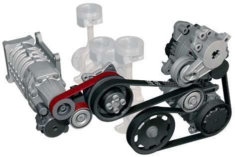

SOLENOID COUPLING:In addition to supplying coolant, the coolant pump has an integrated solenoid coupling for activating the supercharger. The coolant pump, alternator and AC air compressor are driven by the six groove main pulley. The five groove poly V belt of the secondary pulley drives the air compressor of the coolant pump.The compressor solenoid coupling N421 establishes a frictional connection with the supercharger drive. The pulley of the coolant pump is bolted to the drive shaft of the coolant pump. The pulley for driving the supercharger rotates on the ball bearings. The solenoid coil is firmly connected to the coolant pump housing.
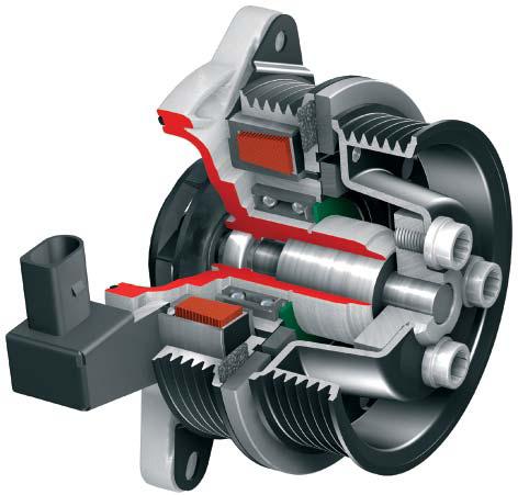
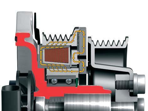
COMPRESSOR SOLENOID COUPLING NOT ACTUATEDThe electrical circuit of the coil is not closed, as a result, a frictional connection is not established (X) due to the spring force between the friction plate and the friction lining. The stationary pulley runs freely on the ball bearings.

COMPRESSOR SOLENOID COUPLING ACTUATED:The electrical circuit of the solenoid coupling is closed by the ECU. The magnetic force pulls the friction plate against the coupling lining. The coolant pump pulley is now frictionally connected to the supercharger pulley.
Think the mods should sticky this for those who want to know how VW's twincharger system works -
Posted

Moderator

Thanks for posting matey
0 guests and 0 members have just viewed this: None.


