


GUIDE : Rebuilding the front end

Posted
#794959
(In Topic #95503)
Settled In

GUIDE : Rebuilding the front end
1. CV Joint - CV joint boots tend to split and this is an MOT failure. After a boot splits you can get grit into the joint in which case it may need to be replaced
2. Driveshafts - You don't normally need to replace driveshafts unless they've been subject to an impact
3. Wheel bearings - These wear over time and you often get a grinding noise when turning in one direction
4. Track rod ends - Adjustments to wheel alignment is done with these and they are often siezed and corroded. The ball joint on the end has rubber which can perish and need replacing
5. Wishbones (including ball joints) - Wishbone bushes tend to wear rather than the wishbone itself and the same for ball joints as the track rod end. In my case the wishbone itself had obviously had an impact and been bent so both were replaced
6. Anti-roll bar - The bar itself is unlikely to need replacing (but can be uprated for stiffer ones to improve handling), it is normally the bushes that are replaced as they perish over time
7. you could easily do the suspension (shocks and springs) whilst you're at it, shocks tend to leak when old and the coil springs can snap
When it comes to working on the suspension I suggest you have large sockets, a big breaker bar and a large hammer handy. You will be hitting some of the toughest nuts and bolts on a car with high torque and likely corrosion due to exposure to eh elements underneath the car. Brain overpowers brute force here - long lever make the job easier, if you try some of this stuff with a normal ratchet you'll hurt your hands and probably fail miserably so get the right tools for the job.
Saying that, these jobs are nice and simple - just nuts and bolts and anybody can do it. Don't be afraid to tackle this sort of stuff because it really isn't that difficult. This is my first go on a Golf and it took me about 90 minutes to strip the car down whilst taking my time and a LOT of photos. You can easily do this rebuild in a weekend or two.
Posted
Settled In
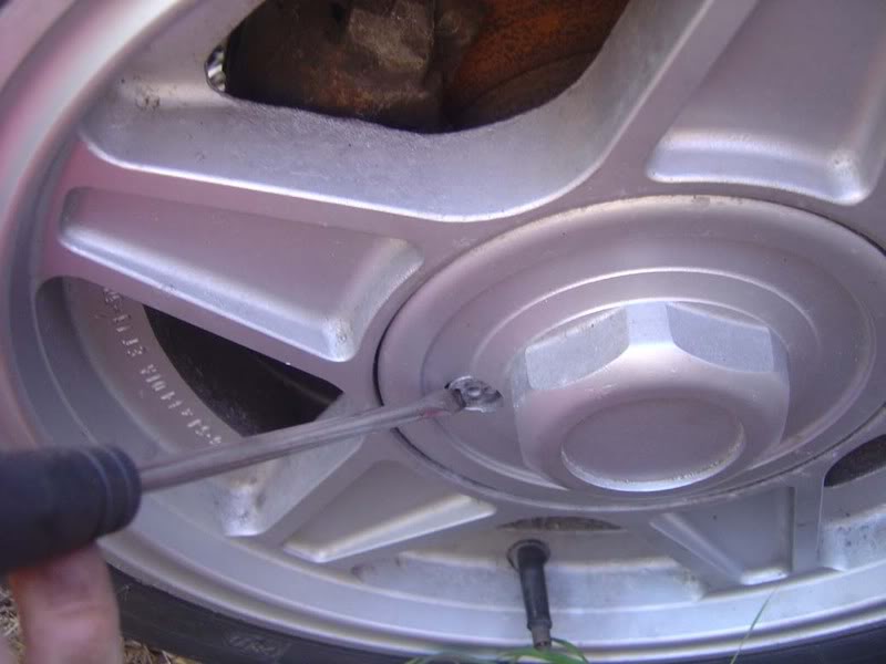
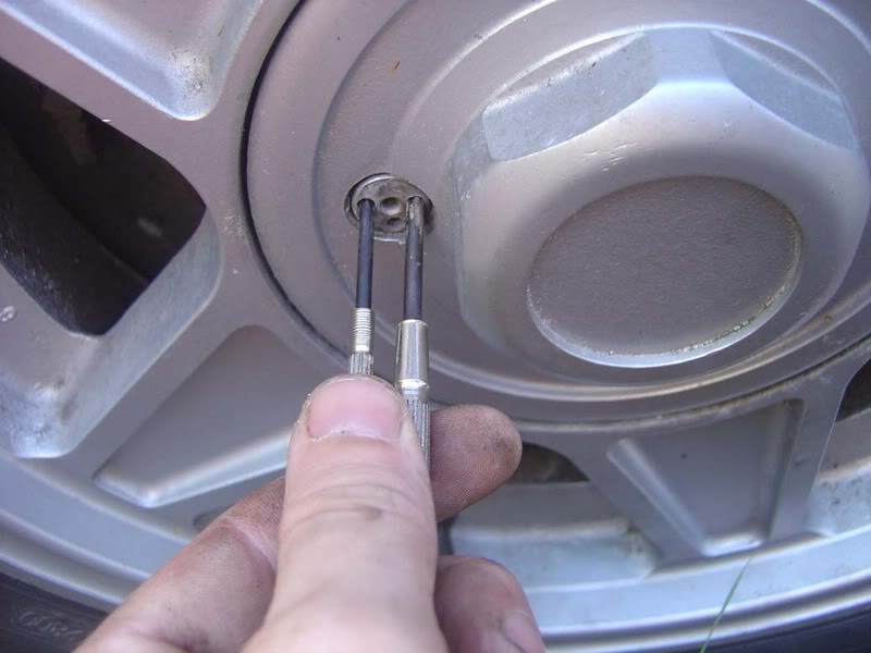
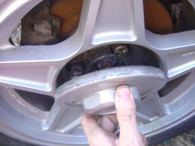
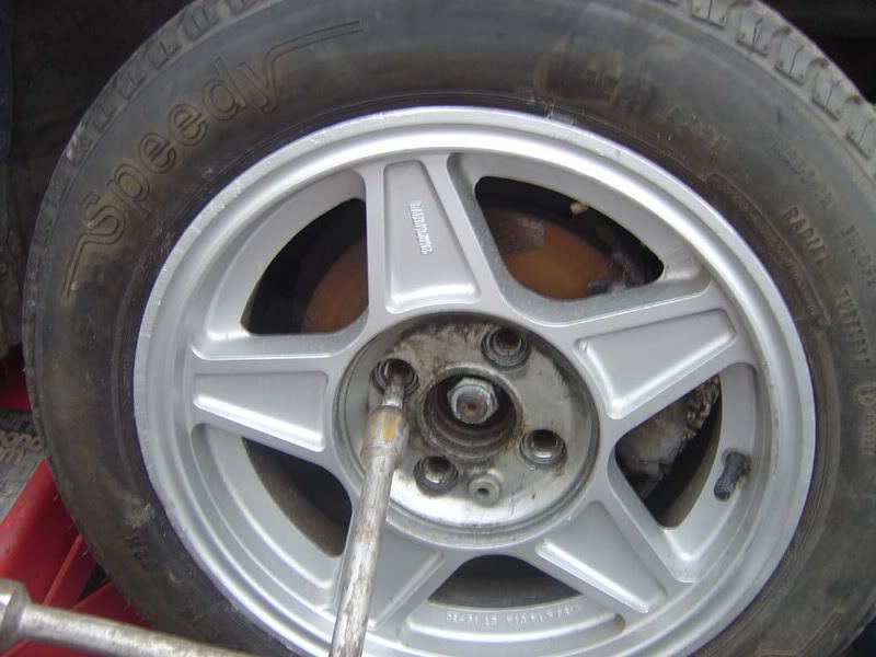
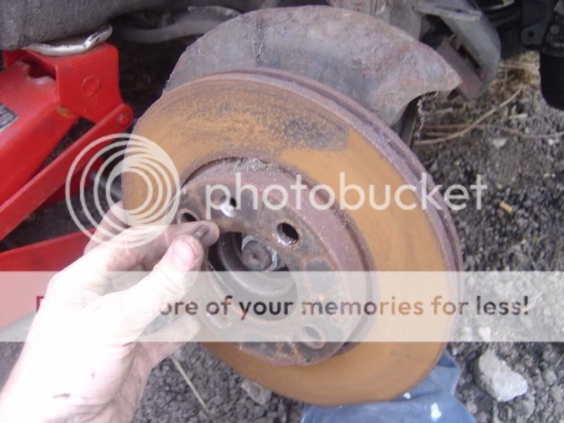
Step 2 - Remove the retaining screw (Picture 1) and pull the centre cap away (picture 2)
Posted
Settled In
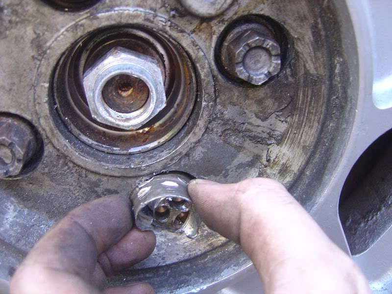
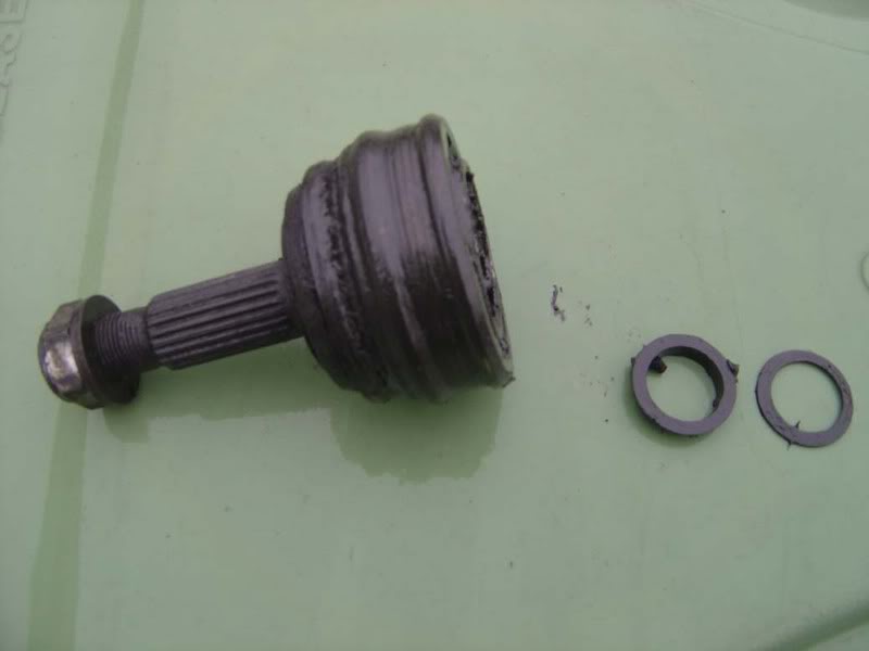
Note : If you haven't got the locking wheel nut key or (as with mine) someone has chewed up the nut, you can still remove it with a bit of determination.
Mine were fitted with a 'collar' that spins around on the outside so you can't grip it with a monkey wrench etc so this was removed by cutting down the collar with a chisel (picture 1).
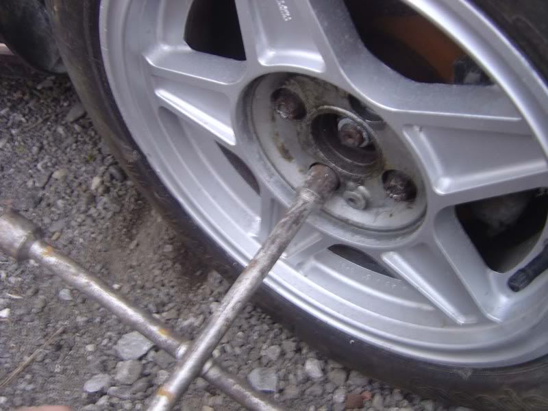
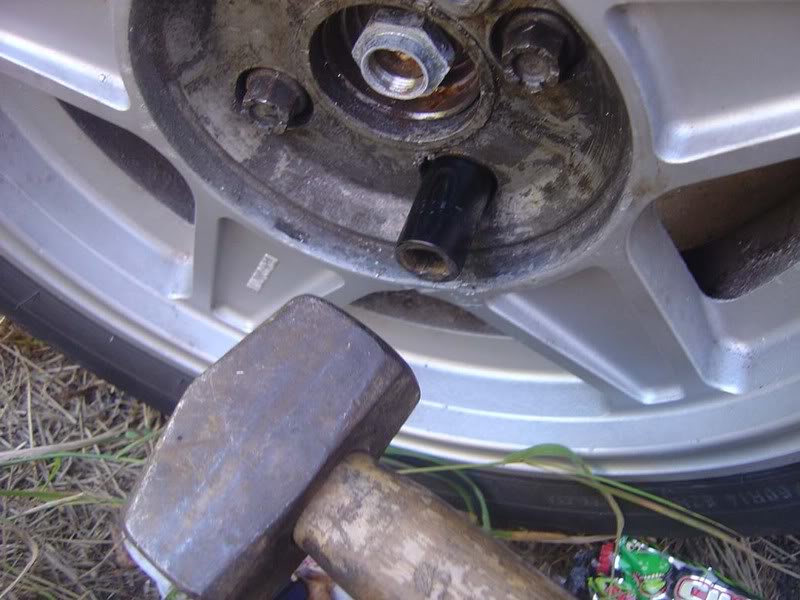
I then hammered a 17mm socket onto the nut (which was about 18mm diameter) to get some purchase to apply force (picture 2). Don't be bashful here (excuse the pun!), you need to carve good edges into it if possible so try not to keep slipping off. Cheap wheel nuts can be 'moulded' easily so make sure yours aren't hardened steel or you'll be there all day!
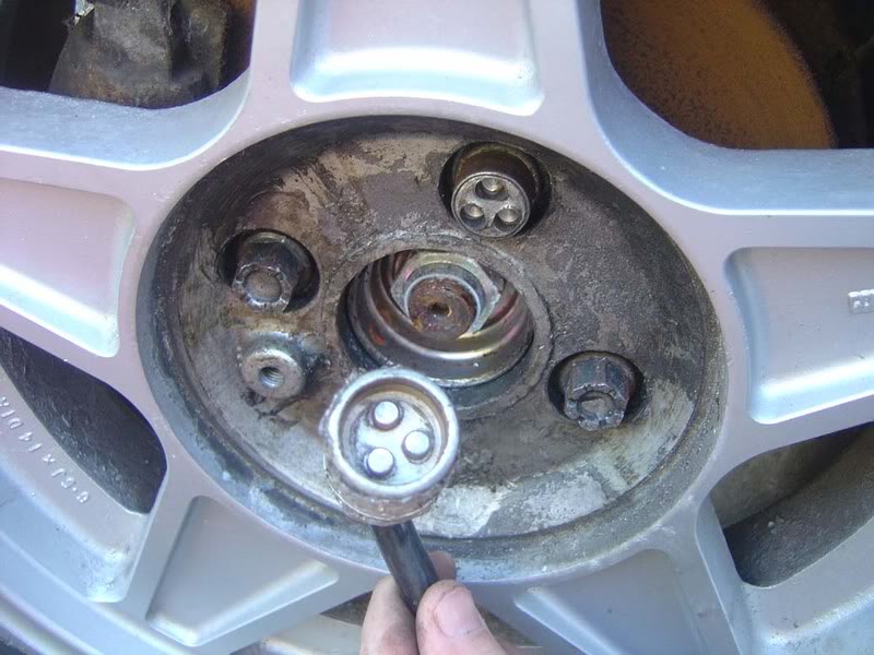
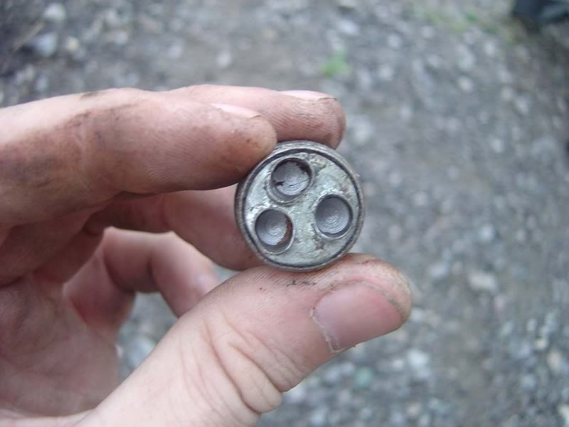
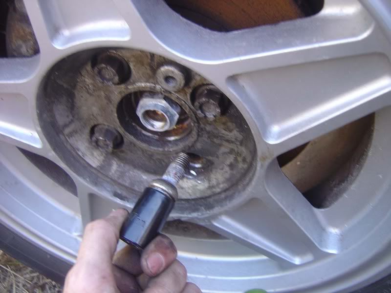
This can then be removed with a normal ratchet and the locking wheel nut will need to be replaced (picture 3)
Posted
Settled In
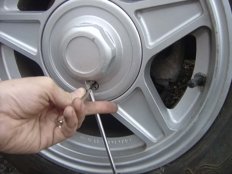
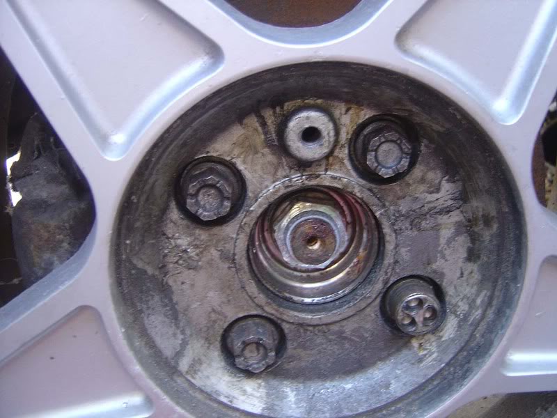
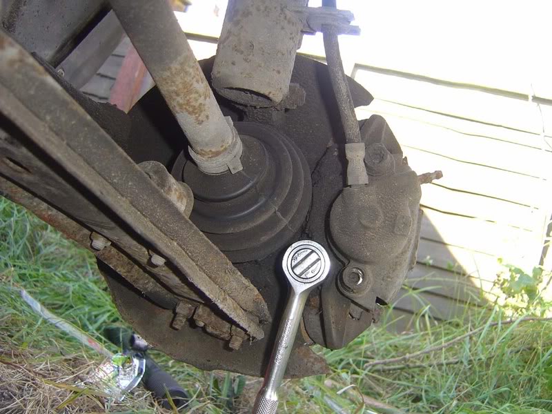
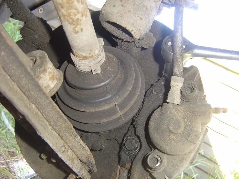
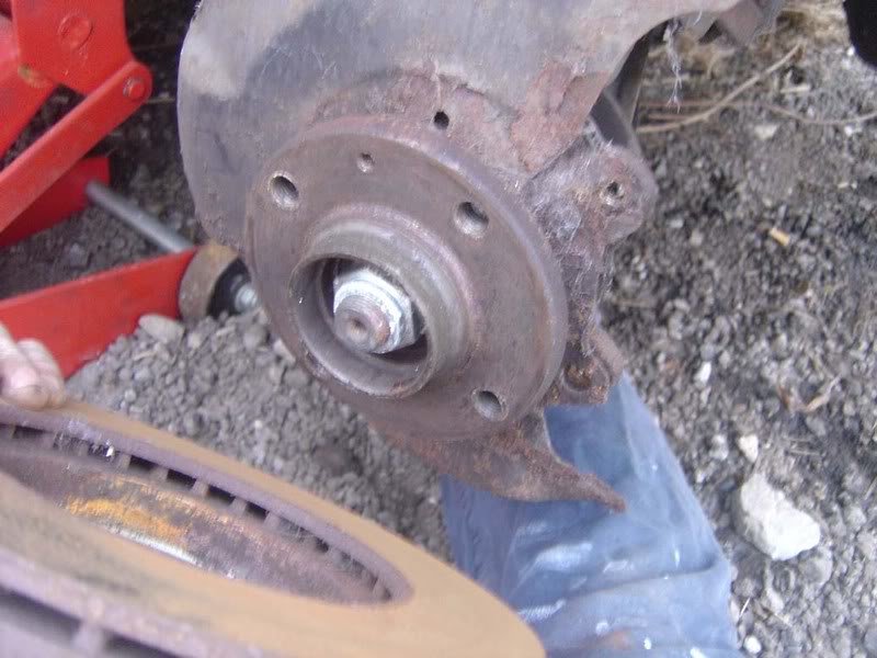
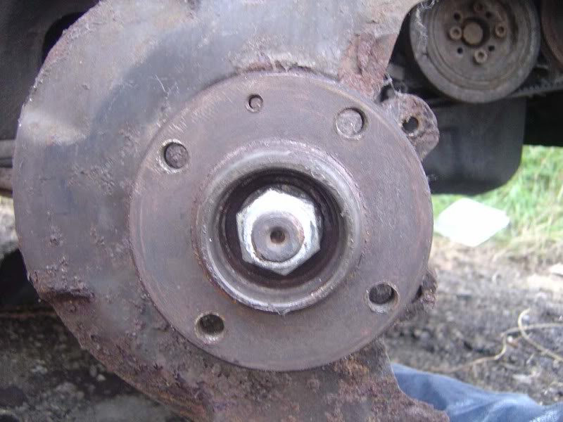
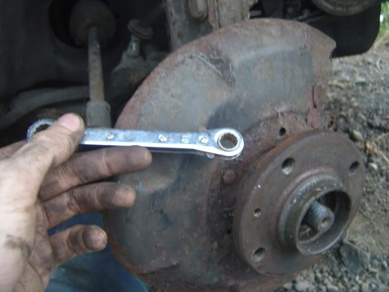
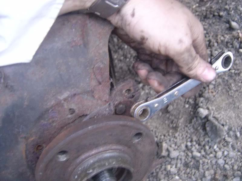
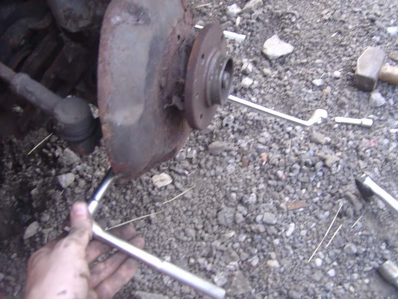
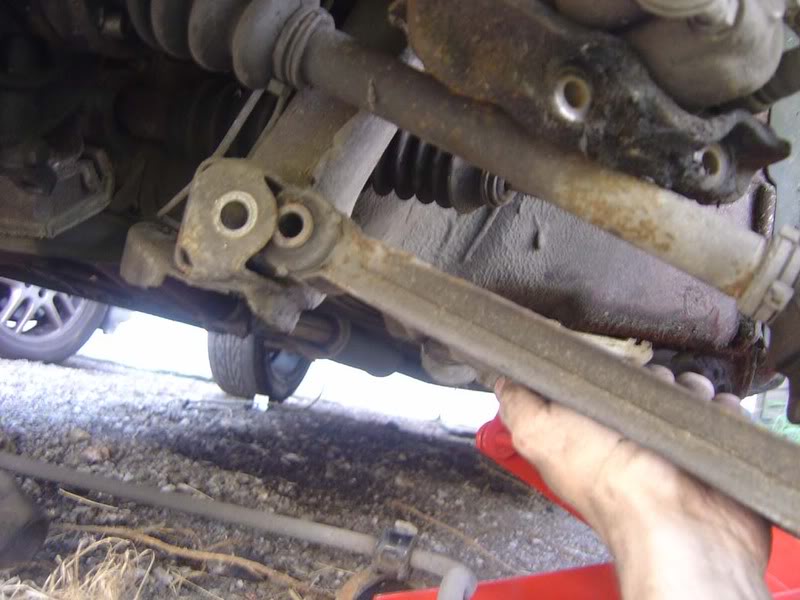
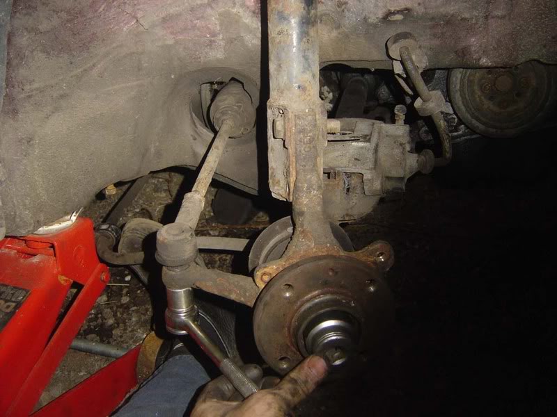
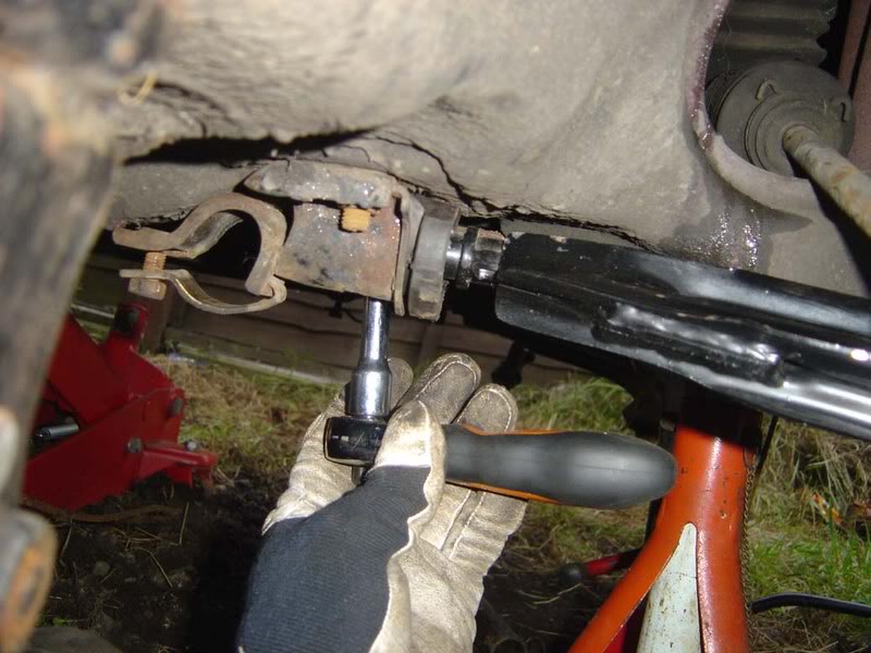
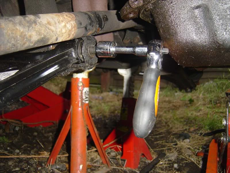
The bolt is shown in the middle of the first picture. To remove the bolt you should use a long extension bar (a 'breaker bar') as shown in the second picture to allow you to apply enough force to undo it. Note that you only need to undo it a turn or two and then it becomes much easier and you can do this with a normal ratchet. For now, crack the nut off two turns .
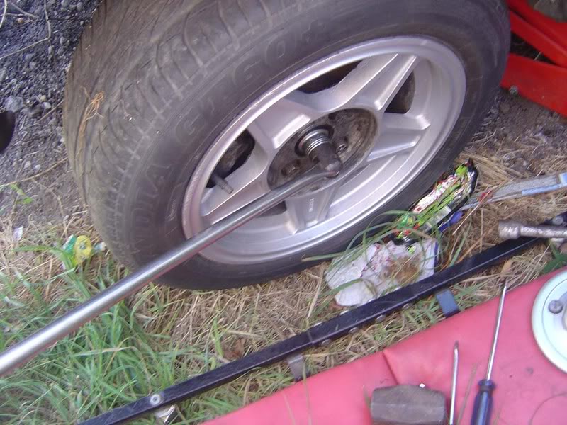
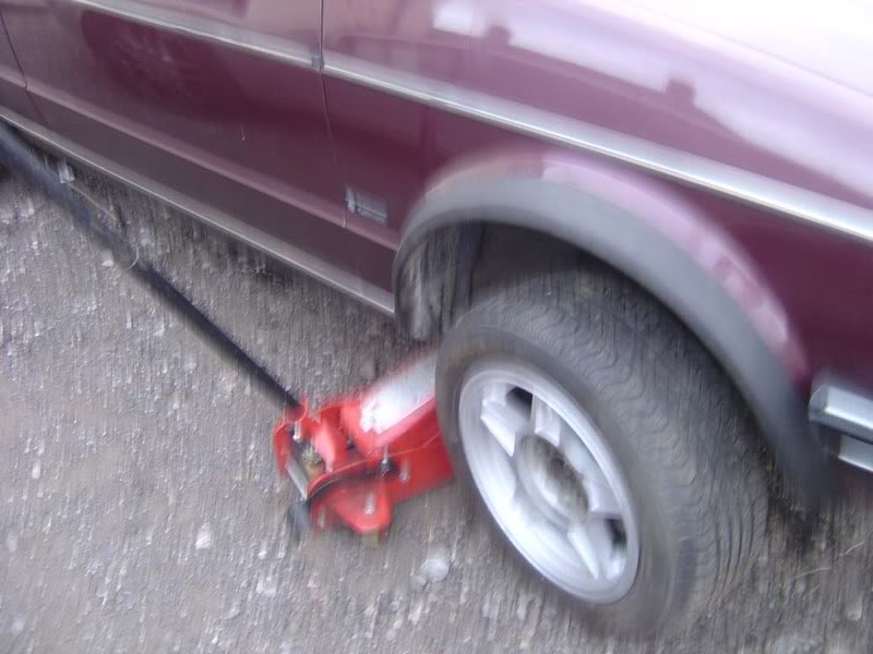
Step 5 - Now you have slackened all the wheel nuts and the driveshaft bolt you can jack the car up and remove the wheel nuts completely and put the wheel to one side (it just pulls off now)
Posted
Settled In
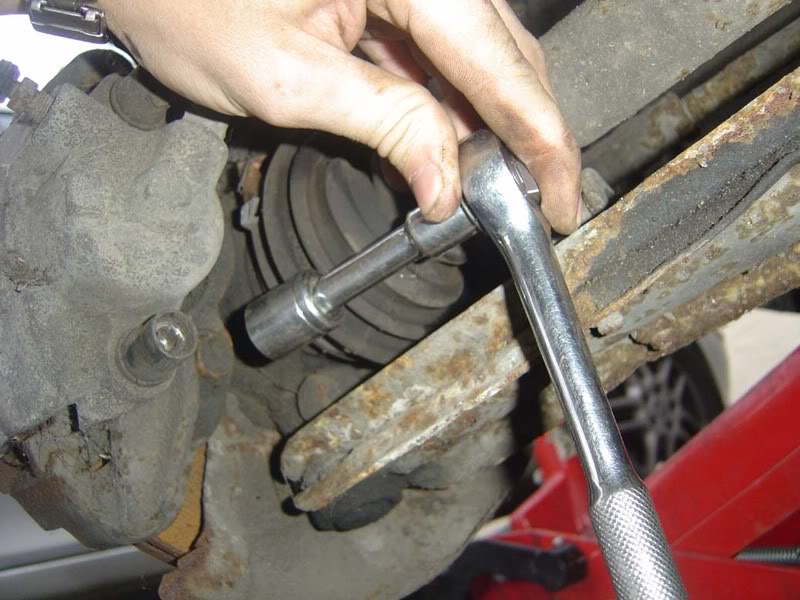
Note the use of an extension bar on the top bolt to get round the brake lines
Posted
Settled In
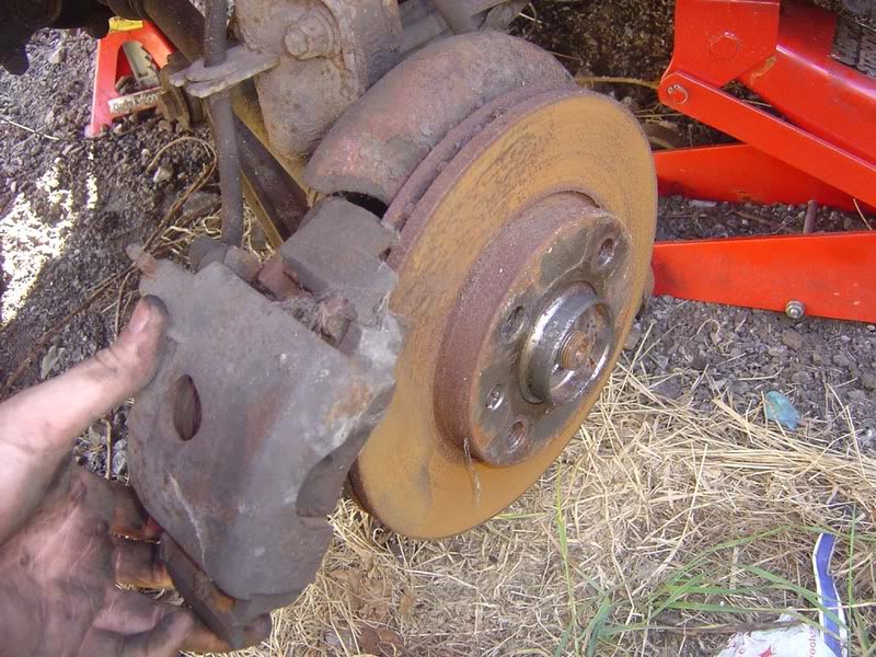
Step 8 - Now onto the brake disc, this is only held on by a short phillips screw. When removing this you can end up with a heck of a job if you sheer the screw head (you then have to drill it out which his a real pain). To prevent this, use some anti seize compound if you have it but most importantly apply a lot of forward pressure towards the disc rather than in turning the screw. Put yourself directly in front of where the road wheel would be and apply your whole body weight down the screwdriver so all your force is pushing the screw towards the disc then twist. This way you won't be likely to slip of the screw and distort the head
Posted
Settled In
Step 10 - Now you can finish off removing the drishaft bolt that you loostened earlier on
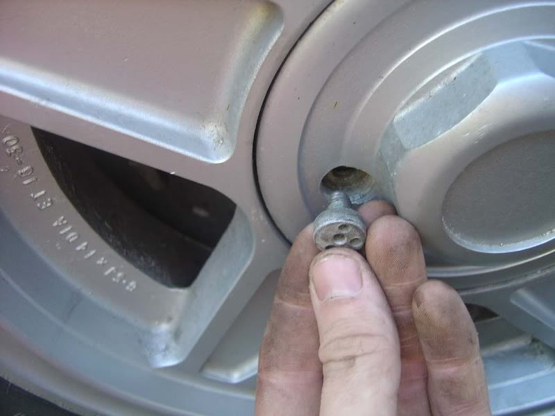
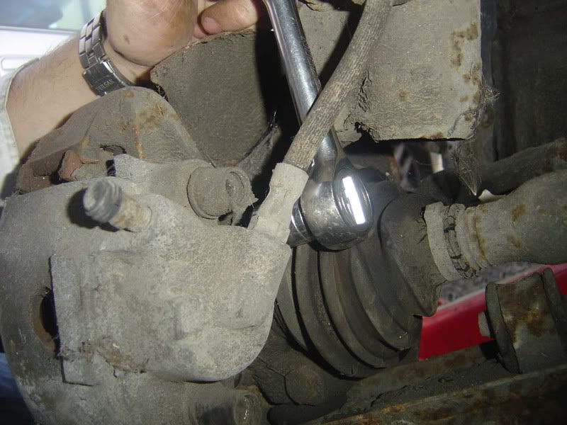
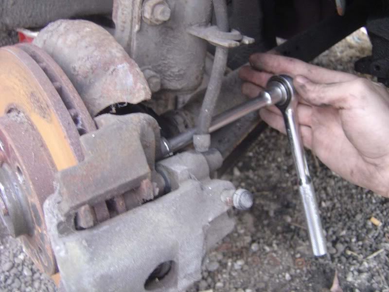
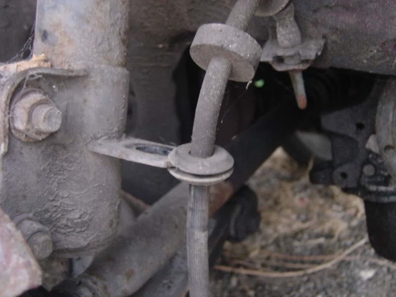
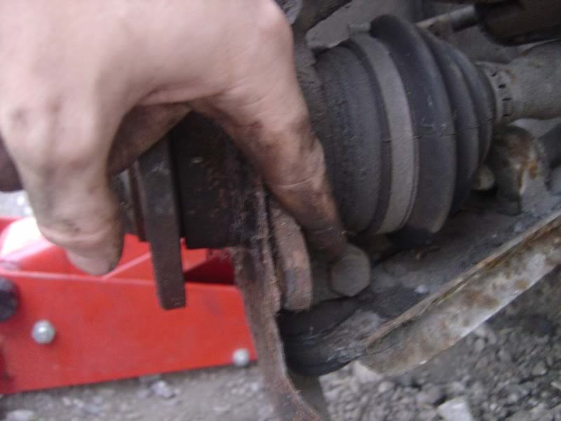
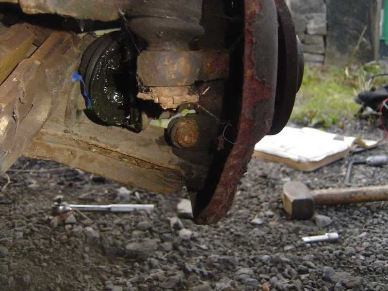
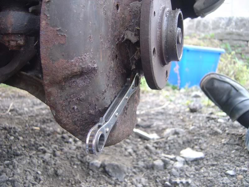
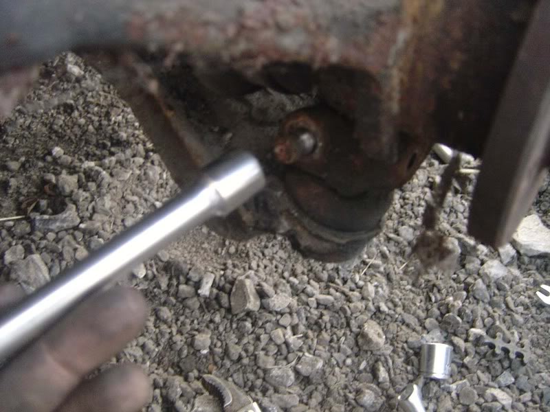
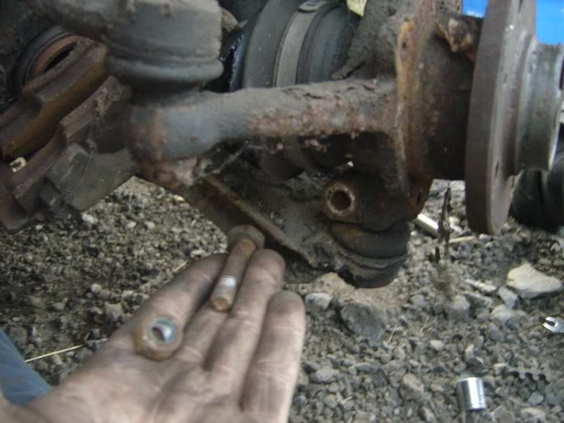
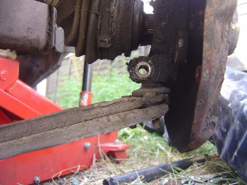
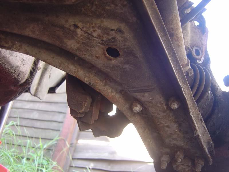
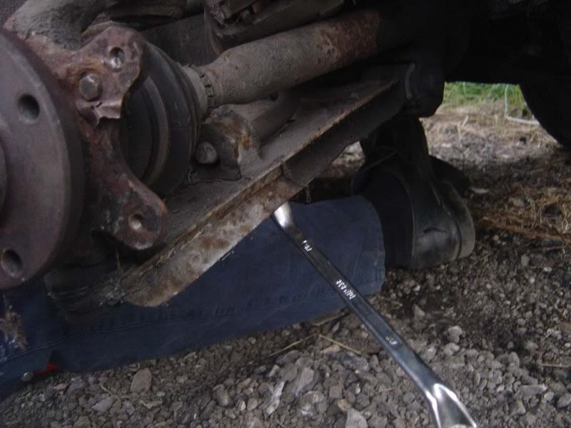
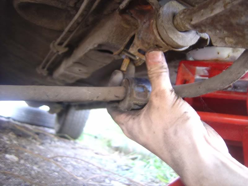
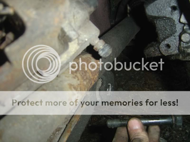
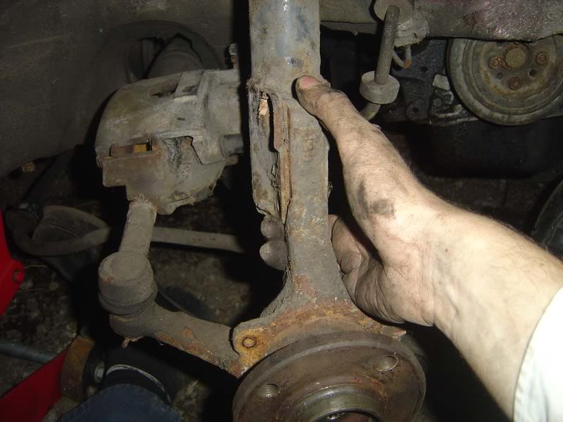
Step 11 - If you now look behind the hub, there is something called a 'pinch bolt' which goes through the bottom of the hub and holds the ball joint of the wishbone in place. Below shows either end of the pinch bolt
Posted
Settled In
Posted
Settled In
Posted
Settled In
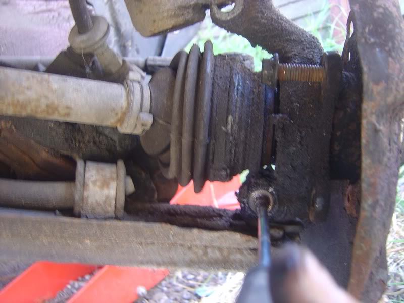
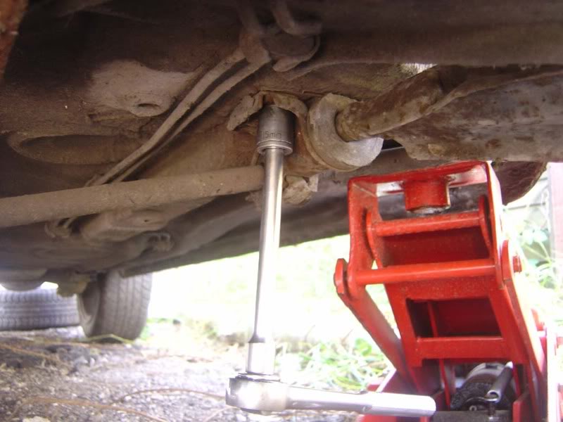
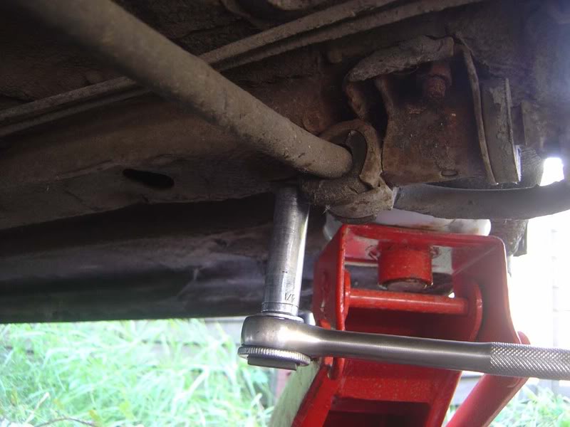
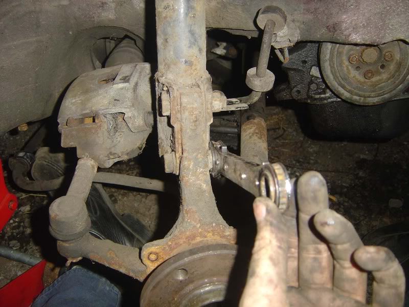
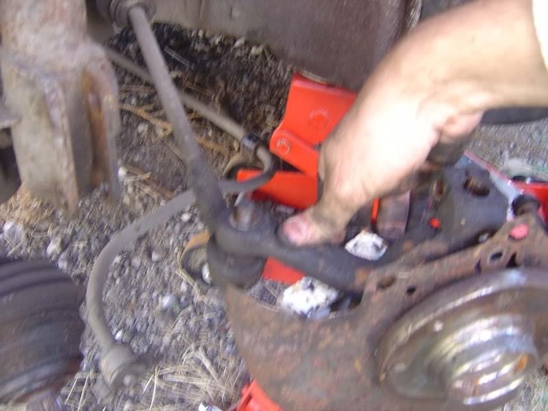
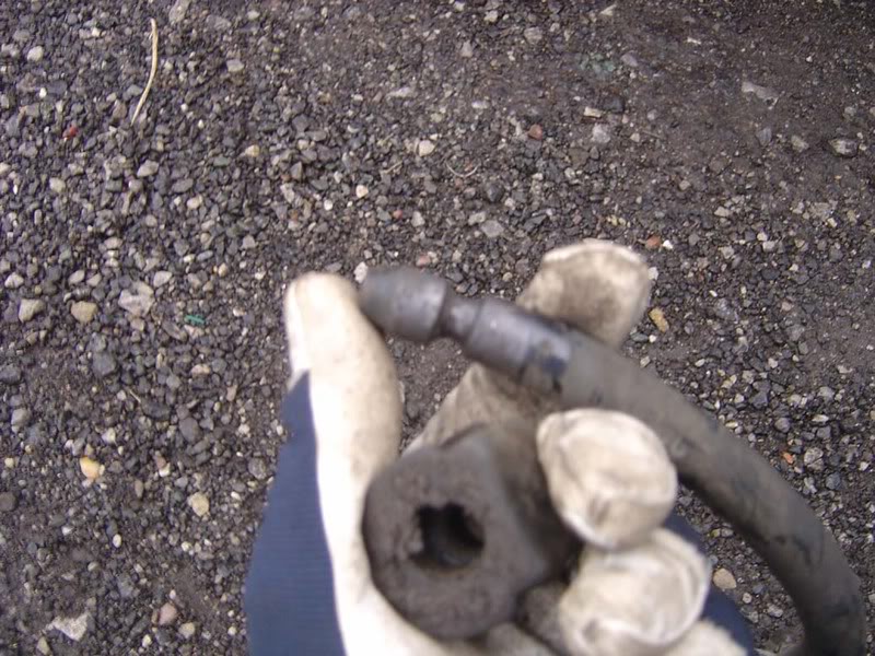
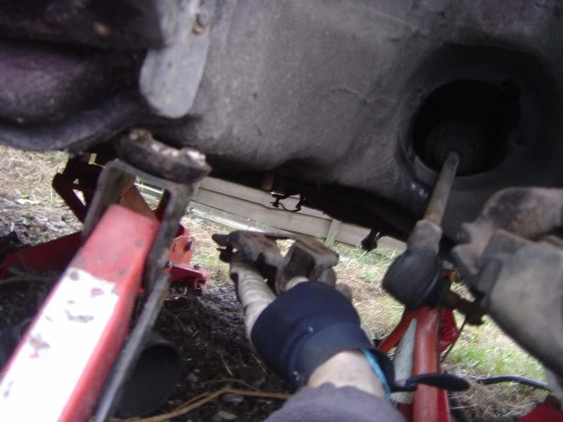
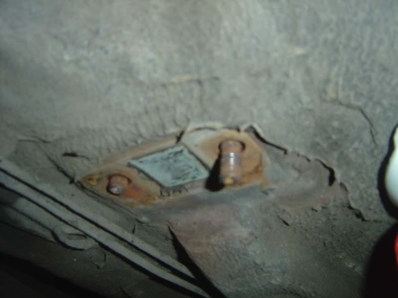
Step 15 - Now we move onto the anti-roll bar, this is attached to the wishbone with two 13mm nuts (See first picture). I found them surprisingly easy to shift and I made sure I released each bolt a little at a time to reduce the stressing on the bracket holding the roll bar down. With the car supported by a jack the roll bar won't be under tension so don't worry it won't 'spring off' when you release the bracket. The third picture shows the short studs that protrude through to the underside of the wishbone

Posted
Settled In
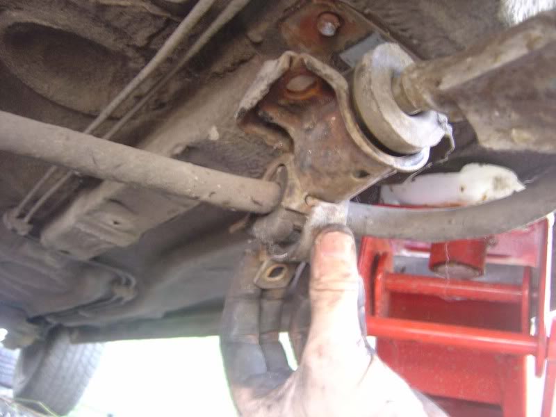
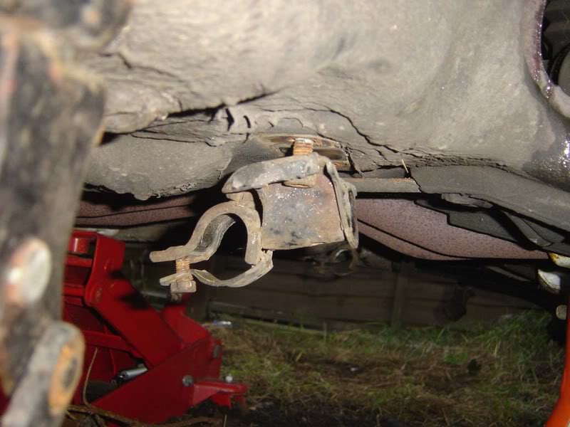
Once removed, you can pull the metal retainer down with your fingers (see picture 3) and the the roll bar will drop away from the car as shown in picture 4.
The 5th image is showing the metal clamp
Posted
Settled In
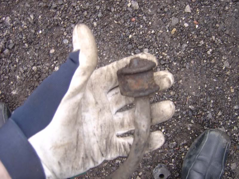
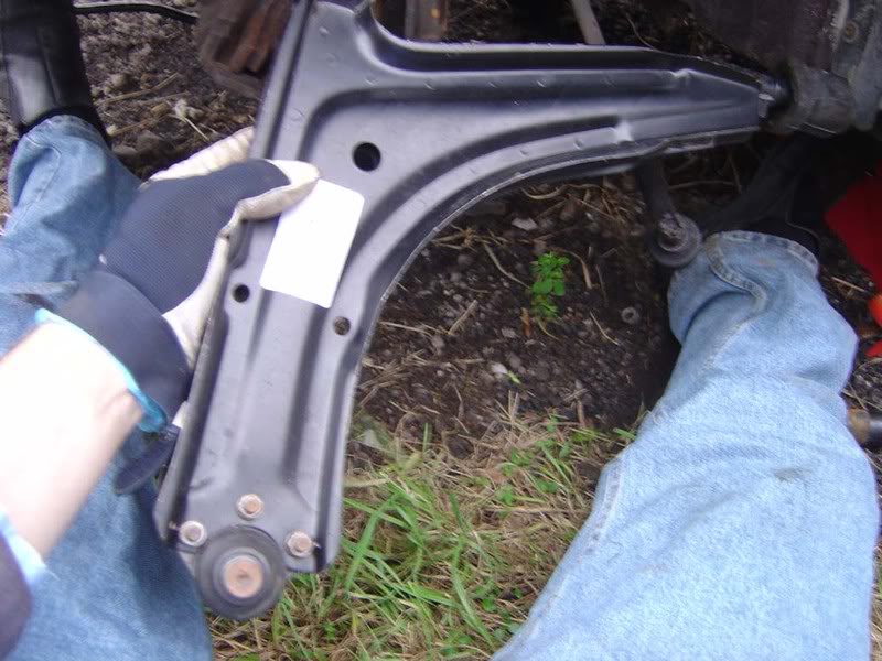
Step 18 - Now the wishbone is free to be removed from the car. To do this, wiggle the wishbone up and down whilst pulling it away from the car and it should slide out quite easily
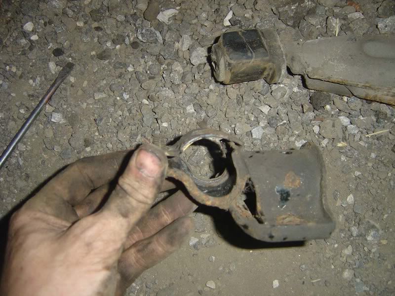
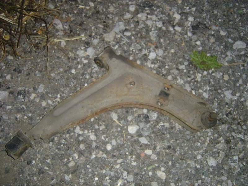
Step 19 - There you have it, one wishbone! You can see at the bottom left there is the rubber mount which was mounted alongside the roll bar. Also there is the ball joint on the right which swivels to allow the hub's angle to vary and finally the top anchor point which has a rubber bush inside it where our large bolts attached the wishbone to the frame.
I've included a picture showing how bent my wishbone was when I decided to start all this strip down

Posted
Settled In
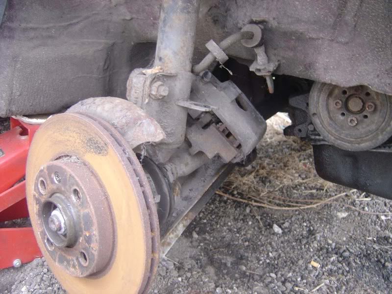
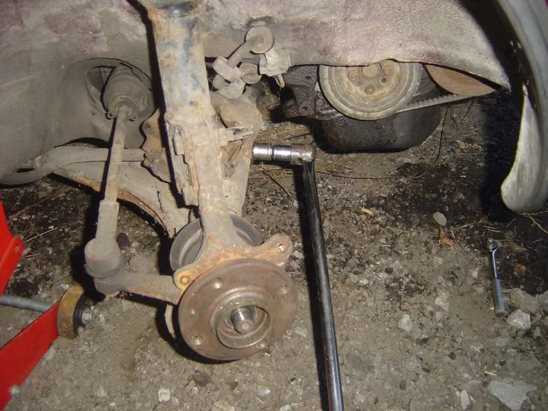
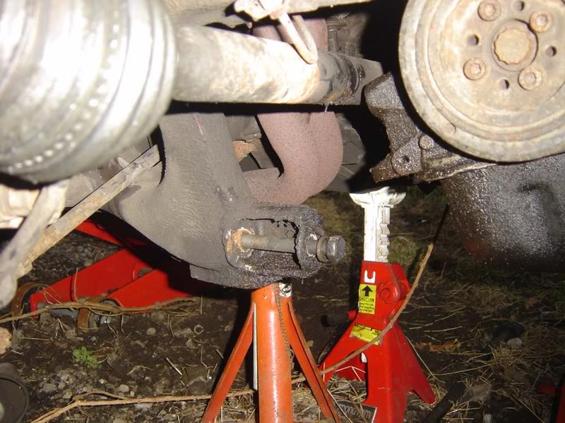
Step 21 - After removing these two nuts, simply ease the hub away from the strut and it should be completely free. If you were changing the suspension, at this stage you would just need to undo the bolts at the top and the shock/spring assembly would drop down for you to disassemble it.
Posted
Settled In
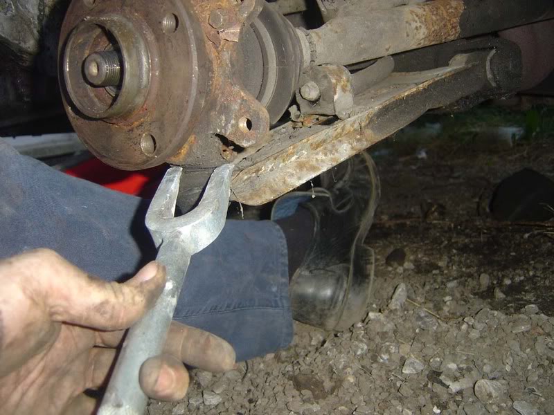
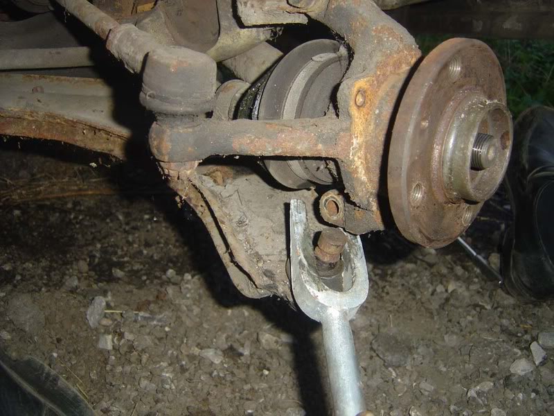
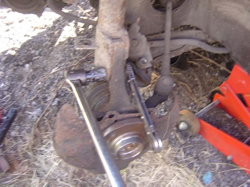
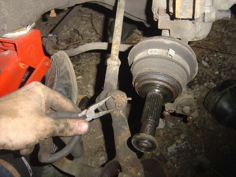
To remove the split pin get a pair of pliers and bend the two 'legs' so they are straightened up and can pass back through the whole they came through (picture 1 and 2).
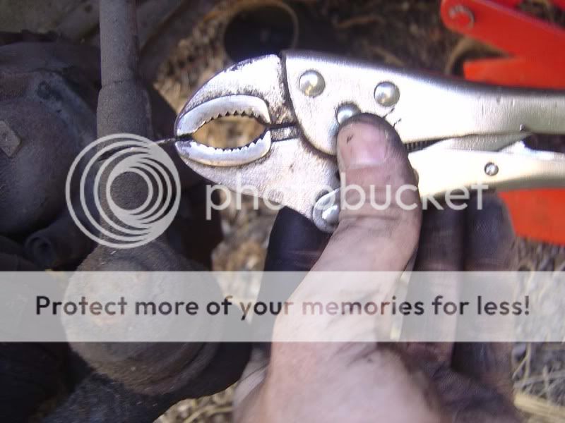
Use a pair of mole grips to pull the pin out (picture 3) - it will probably take some wiggling and bending and don't be surprised if the pin snaps. If it does snap then just pull each half out individually.
Once you've removed the split pin you can fit a 19mm socket to the castle nut and remove it (picture 4)
Posted
Settled In
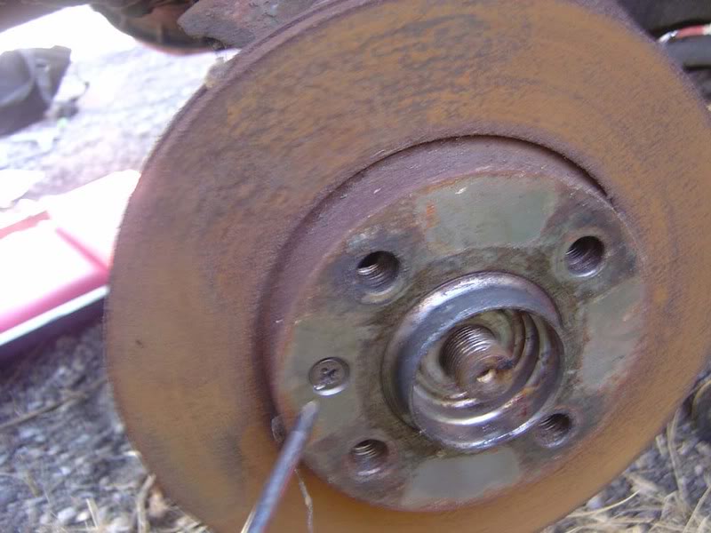
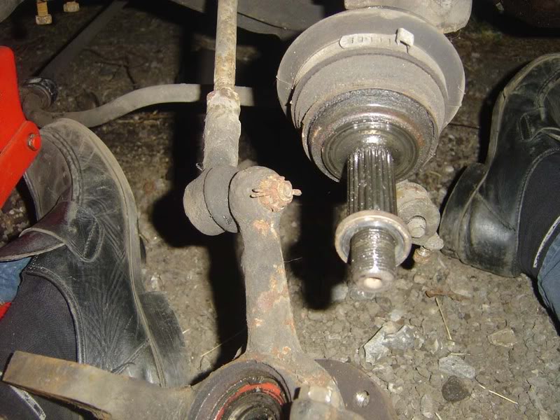
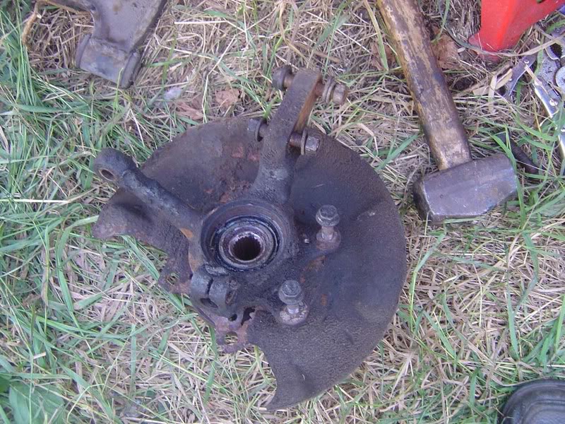
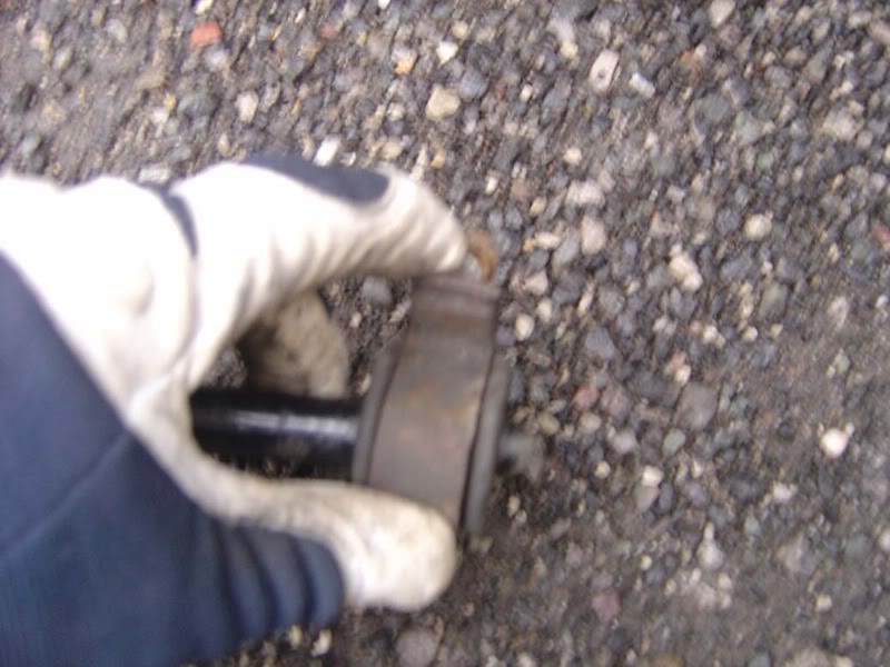
Step 24 - The hub should now come away from the car (it will simply slide off the driveshaft). You'll notice all the nuts/bolts are fitted to the hub - it's easy if you always put things back once you've removed them so you prevent ending up with a huge pile of fasteners and no idea where they came from at the end!
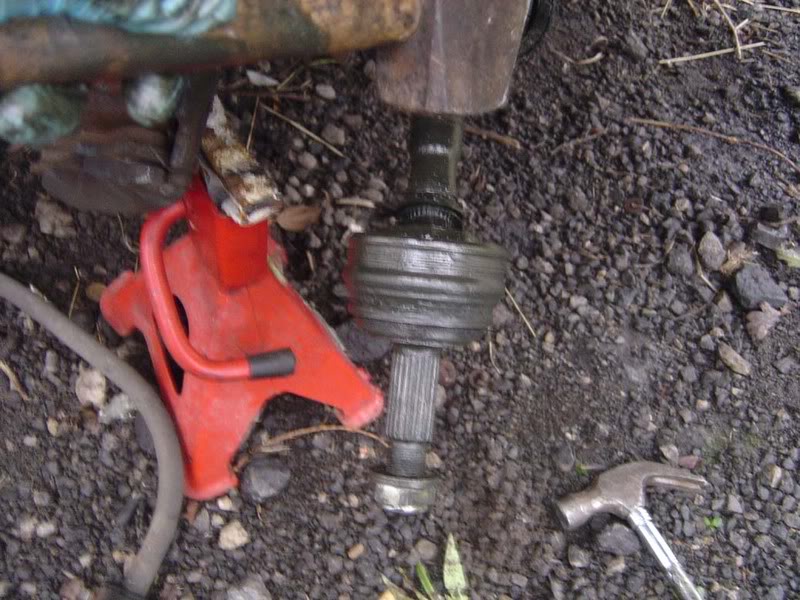
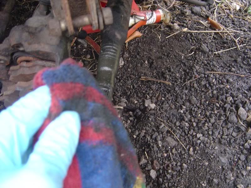
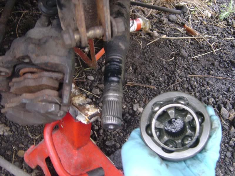
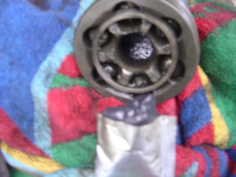
Step 25 - I had a split CV (constant velocity) joint boot so needed to replace this, steps 25-32 cover this. The CV joints simply tap off as shown below
Step 26 - Clean up the drive shaft area
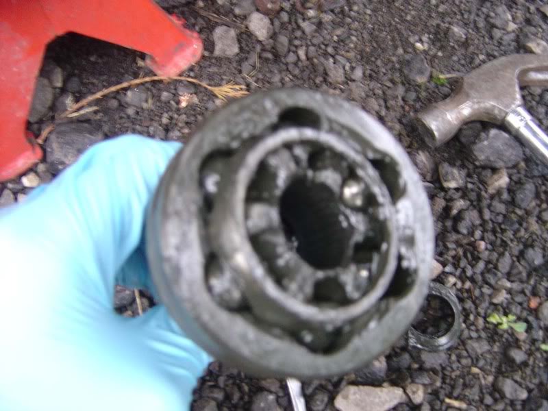
Step 27 - Check for any grit/dirt or signs of wear in the joint. If necessary replace it, otherwise clean out the old grease
Posted
Settled In
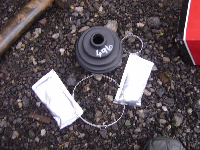
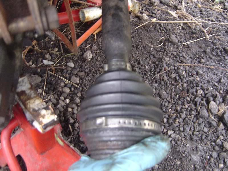
Step 29 - You will have some kind of retainer to fit which is normally a toothed clip as shown. Simply squeeze it (tightly) around the rubber sleeve and hook the teeth into the grooves. You may find it easier to trim some of the excess off the clip itself because they often come with a far greater length than you need.
Posted
Settled In
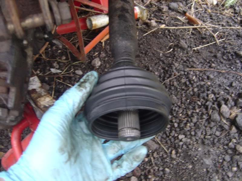
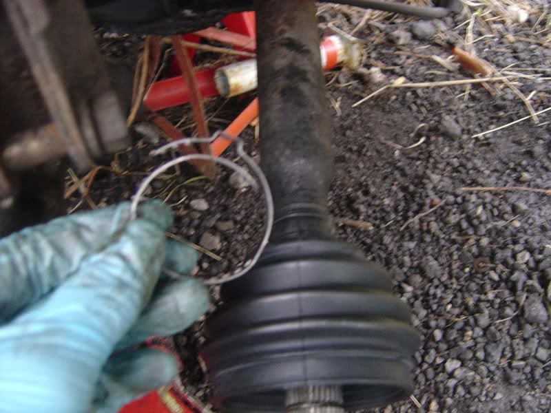
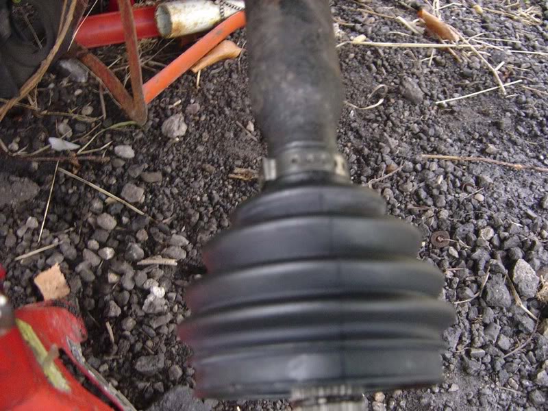
Step 31 - Slide the joint onto the driveshaft
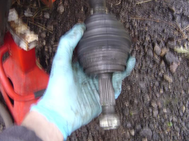
Step 32 - As before, use the retaining clip to hold the joint in place. This one is much larger but again, you may need to trim it to size.
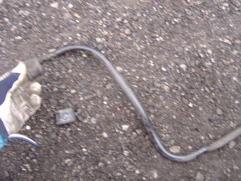
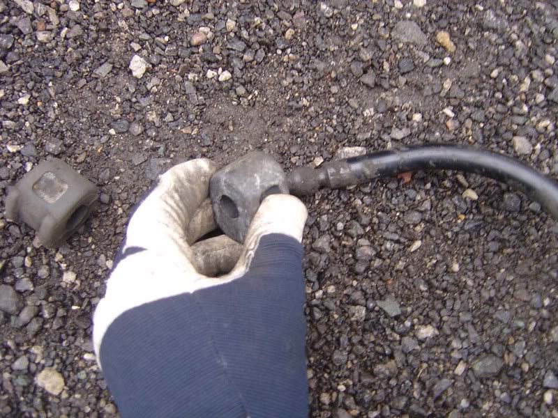
Step 33 - Now, on to the anti roll bar. Pull the metal C clip off the end bushes as shown in picture 1. Then wriggle the bush off the anti roll bar (picture 2). The trick is to apply lots of pulling force and then just wriggle the rubber bush back and forth to help it slide.
Posted
Settled In
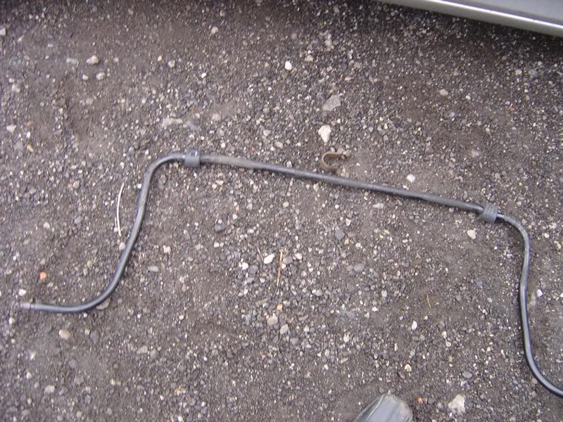
Step 35 - Now for the more difficult one - slide the old bush all the way up and off the anti roll bar (alternatively just cut it off but the act of removing it gets rid of the built up dirt on the anti roll bar).
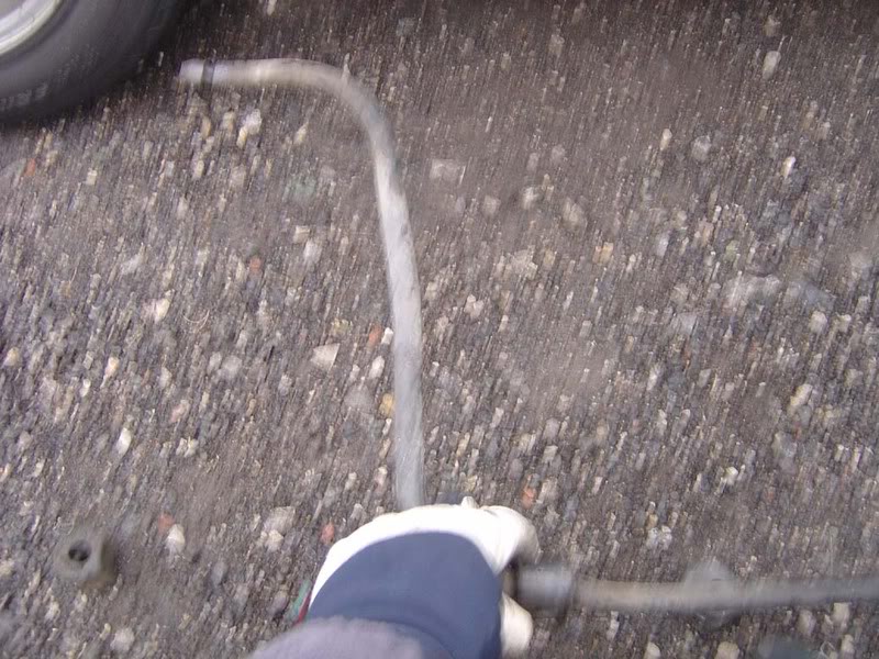
Step 36 - Now go through the same process in reverse, slide the new bush all the way down the bar again (picture 1). Once you've done this, refit the outer bush and then do the same on the other side so you have 4 new bushes (picture 2).
Note you will find the anti roll bar is not that stiff and it may be worth investigating upgrades of the bar itself if you are needing to replace the bushes.
Posted
Settled In
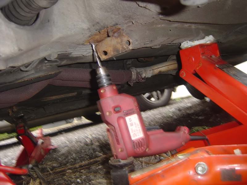
Step 38 - If you have the same luck as me then you'll end up with a broken stud here (picture 1) and end up drilling it out (picture 2) which makes life much more difficult!
Step 39 - Once the bracket is loosely fitted the wishbone can be put into place
Posted
Settled In
Step 41 - You may want to tap the wishbone back in to place (just gently) or do some wriggling to make it slide back into the rear support then it will push straight into the front support with ease.

Step 42 - Now tighten the two 15mm bolts for the rear support
Step 43 - Once the rear support is fixed irmly in place you can use a 19mm to tighten the long front bolt that holds the front in position
0 guests and 0 members have just viewed this: None.