


Mk1 16vg60 build, slowly but surely

Posted
#1464785
(In Topic #193825)
Old Timer

�Spec of the engine;
�9A block, re bored to first size up.
�JE 8.5:1 pistons
�Stage 4 charger, �65 mm pully
�Head flowed and ported, valve seats recut
�Bar tek inlet manifold
�G60 throttle body with TPS
�034 motors ports crank trigger kit
�Bahn brenner integration kit
�Ford gen 2 coil pack
�Bar tek coolant outlet ( points away from charger)
�G60 clutch and flywheel
�02j gearbox with wave track diff fitted and ASD code 5th gear fitted.
� Pedal box converted to hydraulic clutch
�Everything balanced and lightened
� Loads more but this list is probably putting you to sleep so here are a few pictures

�
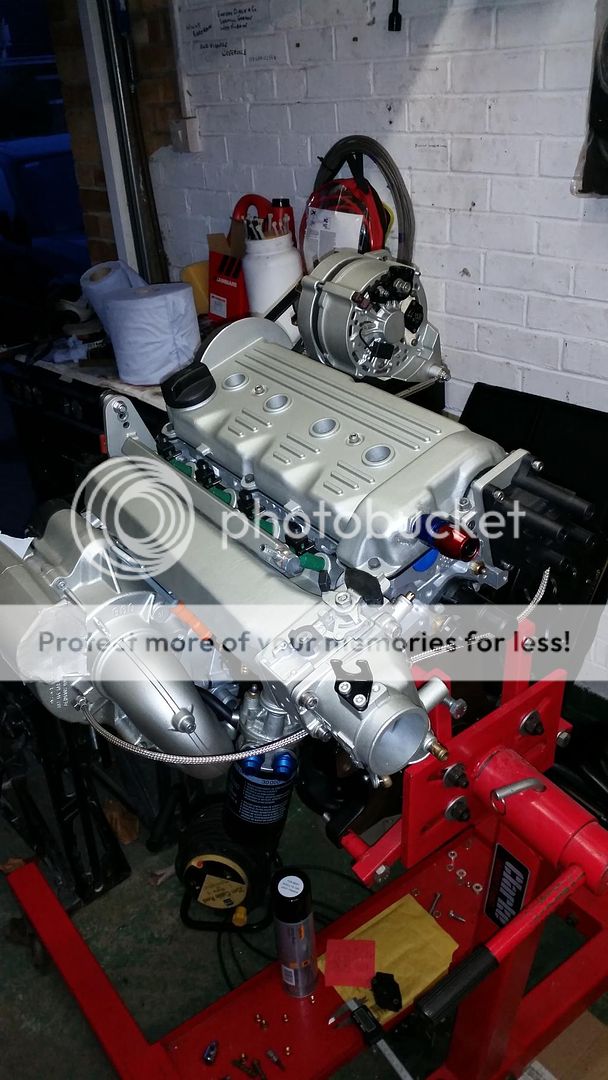
�Here is the engine as it stands, it's taken a good deal of effort to get it to this stage due to having to strip and rebuild it several times.
http://s893.photobucket.com/user/daniboy1_2_3/media/20150123_164710.jpg.html]

� So many issues have cropped up during this build. I'll attempt to document as many as I can remember.
� One of the first hurdles was the fact that my JE pistons had no cut outs for the oil squirters. �After many hours trying to position �them as best I could I realised that I was going to have to strip the engine down and have them machined to be sure there was going to be no trouble, I could just imagine one of them coming off at 7000RPM and that would be game over!.
�So that was the block together again and time to start torqueing it up. Before I got that far I noticed that the crank was perilously close to my new oil pump as I rotated it. �So a little bit of filing and all was well again after a good clean out.
��
�My next problem was my inlet manifold didn't fit correctly meaning the inlet ports needed opening up on the head.�

�The manifold is a bar-tek unit and the fit was very poor . Lots of slop on the bolts and they were biting the manifold unevenly when tightened up. I had some dowls made up for it so i know it was going back on in the same position then spent many hours, filing, refitting, inspecting each port with a mirror until i was happy there was a smooth transition �between head and manifold. It looks brutal but this is much preferable to having a restriction in the path of the air flow as it enters each port.
�I had to whip the head back off, strip and clean it before reassembling it again. Whilst the head was off I noticed score marks in the fresh bores. Out came the pistons and I eventually traced the problem to the fact that the machine shop hadnt re chamfered the small cut outs at the base of the bores! �In I went with a fine file and relieved the edges, the new con rod stretch bolts were now scrap so I opted for a set of ARP fasteners instead.

ARP recommends that the con rods are checked once the new bolts are pressed in for "roundness" due to the force required to press them in. Another trip to the machine shop and they made some adjustments and I was ready to reassemble again.
� With the block in one piece again, new head gasket and head in place, timing was set and I started to look at the serpentine belt tensioning. I noticed that even with a support bracket at the rear the alternator bracket was still twisting when the serp belt was tensioned.

Difficult to see in this picture but the alternator is slightly twisted even without the serp belt fitted and it got worse once the tension was on there. I've fitted a turnbuckle arrangement between the big lug on the alternator and cylinder head to give me the adjustment to line it up properly.

I might have to play around with this once the engine is running to get it bang on.
� In order to fit a big core radiator I needed more clearance from my 180 degree outlet which meant having to pivot it in towards the block. This had a knock on effect as the outlet was now pointing towards the mounting bracket and the original mounting lug no longer lined up. A bit of measuring, cutting and a few trips to the machine shop later i had this.

Chopped down the original rear support bar to give the charger some extra support there.
�Plan is to pipe the fittings you can see on the rocker cover and block back to a catch tank. I've also had a fitting welded onto my sump which the catch can will drain back to.
�That's a very shortened version of the engine build. Many more hours spent fettling, filing and generally trying to get everything to work together nicely.
� I can see why many chose to go down the 20V turbo route, �however from what ive seen and heard i think this conversion shoukd make for a �nippy mk1 golf. I know im limited by the old g ladder but ive alreadt been having thoughts of trying out the G65 units.�
Alongside the engine work I stripped and rebuilt my 02j gearbox. It's an ENJ code found in the mk4 golf turbos which is supposed to be well suited to a conversation like this. This was my first attempt at open heart surgery on a gearbox. I didn't go too far into it, just stripped it out cleaned everything up and fitted the wave track diff in there. I'd say the trickiest part was checking the pre load on the new bearings and shimming it correctly. Again I sought plenty of Advice and took it slowly.


� As for the car, that's been in the body shop around a year having all sorts of issues with a previous restoration put right. I've been told that it will be getting painted towards the end of this month. I'll get some shots of the car posted up here soon.
� Meanwhile im busy trying to finish the last little details of the engine build along with refurbish the running gear etc.
� I've just invested in a DTA ECU and wiring loom and am currently trying to get my head around wiring it all up. There is a thread which i started �over on club gti with some cracking information for anyone wiring up an after market ECU;
http://www.clubgti.com/showthread.php?276517-Mk1-golf-DTA-ECU-wiring&p=2380059#post2380059
. It's slowly sinking in
more updates to follow.�
 Last edit: by daniboy123
Posted

Website Manager


I would get one of these so that you can get the belt tension spot one, also good if you change the pulley size, you don't have to changed the belt as well.
http://www.bahnbrenner.com/vw_audi/products/471/BBM_Billet_Tensioner_Cap
My alternator still flexes slightly now, I had to brace the rear of it to the back of the engine as well, seems to run ok though.
That top breather on the rocker cover may cause you grief, I think you will be filling the catch tank with oil from it. I just have the breather on the front of my block to a oil separator tank. Mine being an 8V block it is only through the small hole that was used for mechanical fuel pumps, but it copes fine. The 16V one is much better still.
I would not route the oil from the catch tank back to the sump. You run the risk of putting emulsified oil gunge back into the system. Just plan to drain the tank every so often. To be honest there should be very little oil caught in it. My first build where the bores were cut too large use to fill it, but we are talking a litre after 3000 miles. With the new build it is still virtually empty after 1500 miles - that does make me happy though.
Looking forward to seeing the next stage !!
Cheers,
Ade

Ade
Posted
Old Timer
�I'll certainly be keeping a very close eye on all of the things you've highlighted. I've got a boost gauge that I'll be mounting in the dash to keep an eye on belt slip. There are two more holes lower down on the serp tensioner mounting bracket that will allow me to up the belt tension a fair bit if I need to. If this isn't adequate ill be investing in one of those caps.
� The breather system was suggested by John Mitchell of JMR and I was also skeptical of feeding emulsified oil back to the sump.�
� Apparently the moisture soon burns off again but ill be keeping another close eye on this also.
� Hopefully the rebuild is going to start around mid march as the car should be back from the body shop by then.
�I'm going to get them to put most of the glass back in along with the headlining before it comes back to my parents garage where the good bit can start
�I trial fitted the engine before the car went to the bodyshop which highlighted a few issues. The clearance between the alternator bracket and the brake linkage was very tight.

��
�I've notched it slightly but will probably take a bit more out.

Mounted my laminova water to oil cooler low down on the front cross member, things starting to get tight in there.

�Overall shots of the engine bay


��
Another issue I had was the drivers side engine mount bolt was fouling the timing belt cover ever so slightly.
� Not sure what I'll do here yet, I may just have to cut into the cover.

Last edit: by daniboy123
Posted

Settled In

Posted
Website Manager
My Laminova works well on mine, how did you mount it in the end? I found these:
http://www.speedflowshop.co.uk/laminova-bracket-pair-3519-p.asp
But baulked at the P&P that they wanted !! So made a pair myself.
I had to do a fair bit of cutting on the lower timing cover to clear everything. I got a brand new top one and had to cut the lower indent off and then I made a piece to fit in the whole to keep the whole thing flat
Looking forward to the March progress !!
Cheers,
Ade
Ade
Posted
Old Timer
Keep up the good work�

Might tempt me to go this route and I haven't even got my 8v G60 on the road yet lol
Posted
Old Timer
� I did the same as yourself ade, made a couple of brackets up to mount the cooler. Here it is tacked in place.�

�The Mount closest to the inner wing was a pain and it means the outlet from the cooler will have to come through 180 degrees back towards the water pump but hopefully it should be okay.
� It was only after I'd made the brackets the other way that I remembered that part of the loom runs across the front cross memeber so I've made the brackets to allow the loom to pass behind them.
�It wasn't long before I realised that I was going to have to rotate my battery 90 degrees to give me enough clearance for my intercooler pipework.
� The oil fitting on the top of the cooler is also going to be very close to my intercooler pipe so that's going to require some work when I get it all back in.
��
Last edit: by daniboy123
Posted

Local Hero

I need one of those spring compressors to fit a belt to a G60.
Posted
Website Manager
There was a guy over on Edition 38 building them a few years ago, he did a limited run - all stainless as well !!
Cheers,
Ade
Ade
Posted
Old Timer
� Think the seller's name was nino or something similar but the thread will still be there on ed 38 and think dubforce as well. I don't think he was making any more after being messed about a fair bit with them.
� Jobs today are clean and inspect the wiring loom :/. Plan is to renew the fuel pump wiring from the fuse box connector all the way through for main power and supply. I'll be using the factory relay slot number 2 but with a different relay, �number 80, which is configured to accept a signal from my DTA ECU to switch the pump on with ignition.
�I'm using the main coil feed to power my coil pack so I'm going to replace this connector and wire also for peace of mind. It's this big chunky blighter at D23 here

�I'm going to add�two relays to the top of the fuse box one for my innovate MTX-L wide band lambda sensor and the other for my ECU power. It was recommended that I keep them separate from the fuse box like this.
�Not done much wiring like this so it's another learning curve, doesn't look too bad, just taking it slowly
. I'll get a few more pictures posted up later.��
Last edit: by daniboy123
Posted
Website Manager
Using relays to switch a clean 12V supply from the battery are great. Guarantees a great supply with the correctly rated cable and no more stress on the switching device other than a relay coil. I used them for both the main ECU feed and the sensors - may be different on a DTA though.
Wiring is a methodical slow and steady process. I got all mine done, but she wouldn't start :-( turned out I had the wires to the trigger wheel sensor reversed, simple but it gave me that "oh no, what the heck can it be moment of frustration" !!!
Enjoy your afternoons work :-)
Cheers,
Ade
Ade
Posted
Settling In


Posted
Old Timer
� Just got this wiring to get my head around and then pretty much ready to start putting the car back together as soon as the painting is finished.�
Posted

Old Timer


Posted
Old Timer


�I've been stripping the loom of unnecessary wires, �to do this I've had to strip away the outer protection. A fair few wires will be running to different positions to how they were originally so this will make that easier.
�Here's a few shots of the tangled mess I've got myself into


�If anyone can recommend a good product to re wrap my loom with that looks good that would be appreciated.�
Posted
Old Timer
It's the cloth type and doesn't tear easily. Made a good job of my loom.
Posted
Old Timer
� I've just ordered a load of cable and connectors so I can start wiring up my relays and repairing my loom along with replacing a few of the more important power feeds and grounds.
� On the look out for a good soldering iron now.
� Hopefully get all the wiring sorted this week.
Posted
Website Manager
http://www.maplin.co.uk/p/pro-iroda-solderpro-120-gas-soldering-iron-kit-n15ar?gclid=Cj0KEQiA6JemBRC5tYLRwYGcwosBEiQANA3IB3W-jXs_LF-RoG8NetObV-cAtekSgsd4jPPhRrjWH9AaAncC8P8HAQ
It's great because you can whack up the heat for the more stubborn larger connectors. Very fast heat up and no wires !!
Cheers,
Ade
Ade
Posted
Old Timer
Posted
Website Manager
The first one I bought was not very good and packed up after about 6 months.
But this version is great.
Being able to increase the temperature is great especially when you have to solder outside or inside the car.
I have had mine for 3 years now and it has been faultless.
You can even use it as a mini blow torch, I often use it to light BBQ's at club events !!
Cheers,
Ade
Ade
0 guests and 0 members have just viewed this: None.